Wireless Joystick Hookup Guide
 Alex the Giant
Hardware Hookup
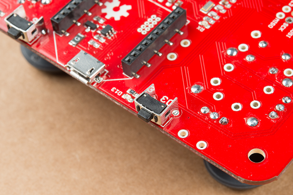
The first step is to solder in the right angle tactile buttons. These are meant to inserted from the bottom the board and soldered to the top layer of PCB. This will look like the image below.
The way the rest of the board is soldered really depends on what it will be used for. There are few different configurations for the joystick(s) and buttons. Read on to see he different configurations.
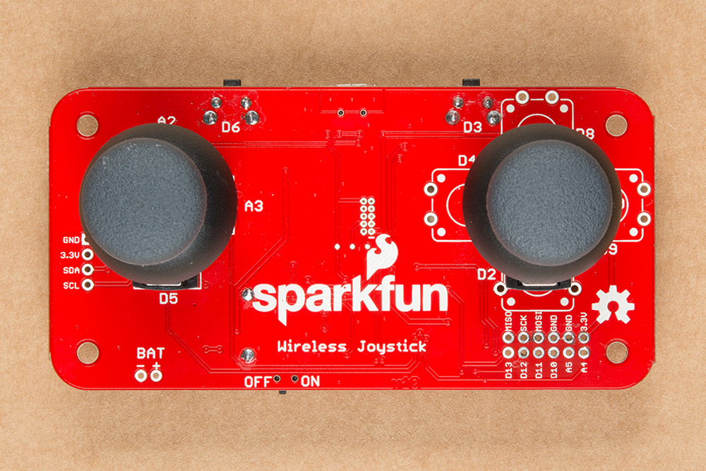
Dual Joysticks
In this configuration, the Wireless Joystick uses both joysticks and is perfect for tank steering robots. Tank steering maps the vertical position of the left and right joysticks to the speed and direction of the left and right motors of a robot. After soldering in the joysticks, the board should look like this:
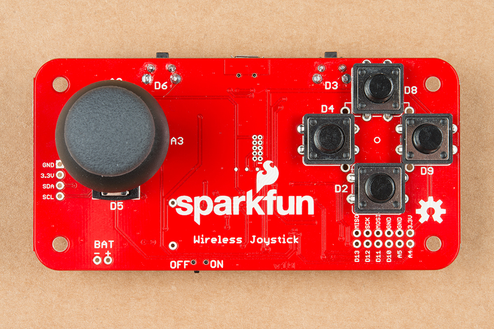
Single Joystick
In this configuration, the Wireless Joystick uses a single joystick on the left and 4 of our 12mm momentary pushbuttons on the right. This setup is similar to what older console game consoles used. After soldering in the joystick and switches, the Wireless Joystick board will look like the image below.
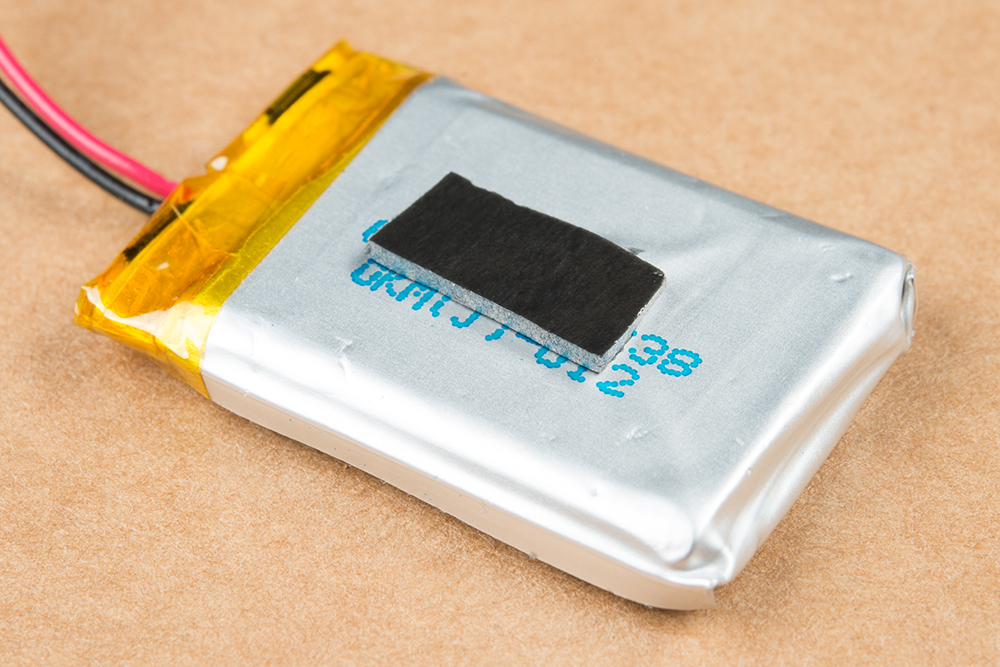
Mounting the LiPo Battery
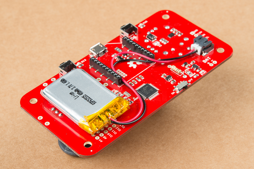
To secure the battery to the board, we recommend using a small piece of foam double sided tape. We've found the easiest place to put the battery is under the right joystick. Before mounting the battery, make sure to trim the the joystick solder joints to avoid puncturing the battery!

Setting the Battery Charge Rate
By default, the charge rate is set to the maximum rate of 500mA. If you're battery is larger than 500mAh, you can skip ahead to the Arduino Examples section. If you're using less than a 500mAh battery, you should solder in the appropriate resistor that we'll determine below.
The life of a lithium battery is dependent on a few factors: number of charge/discharge cycles, charge/discharge rate, battery temperature, as well as a few others. When charging a lithium battery, it's recommended not to exceed a 1C charge rate. For example, if you have a 400mAh battery, your current to charge the battery should not exceed 400mA. To change the rate, move the solder jumper so that the middle and R_PROG pads are shorted. Then solder in the appropriate resistor. To calculate the right resistor, use the equation below:
R_PROG = Resistor value in kohms
I_PROG = Desired current value in mA
To charge the battery, simply plug in the micro USB cable, and move the switch to the OFF position. If your charge rate is below 200mA, the board should charge without issue regardless of the power switch position. Faster charge rates may require the switch to be off to cut current to everything but the charging circuit if charging from a computer's USB port or small USB chargers.