Wireless Glove Controller
 bboyho
Hardware Hookup
Modify the XBee Shield
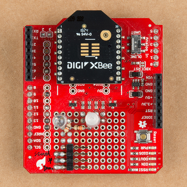
Using the circuit diagram from earlier, solder the components to the XBee shield. Then strip solid core hook-up wire and solder them between the pins. If you are following along, your board should look similar to the images below.
 |
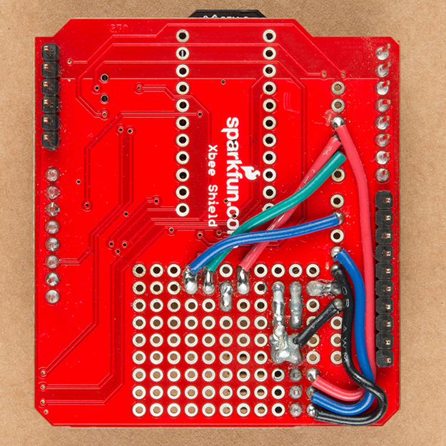 |
| Top View Components Soldered on XBee Shield | Bottom View with Wires and Jumpers |
Making a Connection Between Hard to Soft Materials
Grab four 12" F/F jumper wires of different colors and cut them in half. At this point, we'll need solder a wire loop from the standed wire so that we can easily connect the conductive thread to each of the finger's snappable pins. The other option is to thread the stranded wire through one of the holes on the snappable pin and solder them together.

Securing the Boards and Wires to the Glove
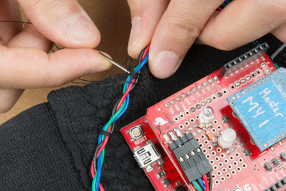
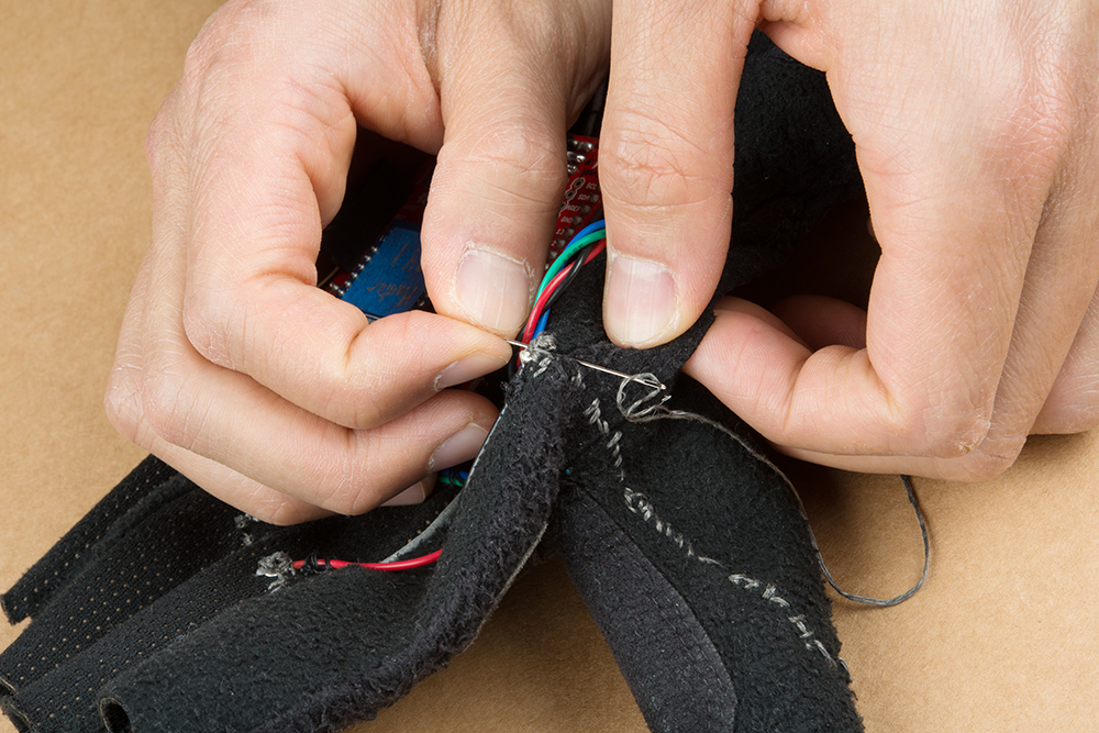
When you are finished, grab a needle, thread the non-conductive thread through the eye, and sew the RedBoard's mounting holes to the glove of your choice. I found that three of the holes was sufficient enough. Make sure to not sew the top and bottom of the glove together. Stack a configured XBee, XBee shield, and RedBoard together. Then insert the female housing into the right angle headers of the shield.
Braid the wires together and secure it to the glove using some non-conductive thread. For each wire, you will need to separate the wires as it gets closer to the fingers. Make sure there is enough space between the board and connections so that the board is not pressing against the wires. Test it out to ensure that there is enough tolerance so that the wires do not get damaged when the hand is moving.
Sewing the Custom Buttons
To make a connection to the snappable pins using conductive thread, we'll need to use a small needle. The two small needles provided in the needle set will be needed to sew the pin down. Find a spot for the snappable pin to make contact with the other finger. We'll start with the thumb. Grab the small needle, thread the conductive thread through the needle's eye, and sew the pin down. Sewing one of the four holes with conductive fabric should be sufficient enough if you loop it a few times. You could use non-conductive thread on the remaining holes. Again, avoid sewing the top and bottom fabric together.
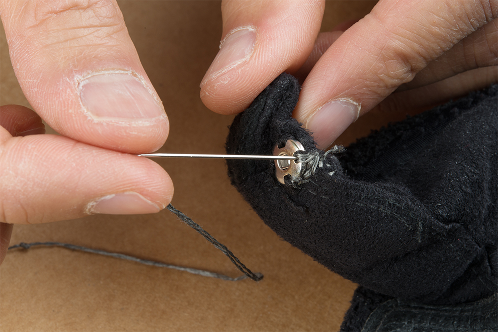
After a few loops around the the snappable pin's hole, make a running stitch to the top of the hand and make a connection to the wire loop to the respective pin connection. Following the circuit diagram, the thumb should be connected to the GND wire. Tie and cut off any excess thread.
Repeat for each snappable pin.

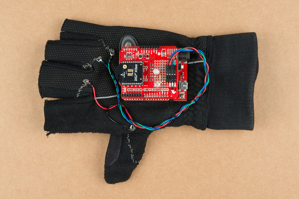
Assembled Wireless Glove Controller
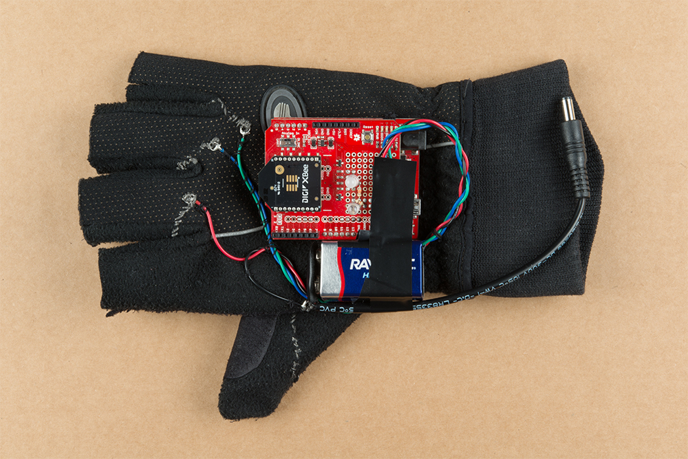
When finished, your glove should look like the images below! Feel free to click on the images for a closer look.
 |
|
| Top View | Bottom View |
If you decide to use the glove remotely, add a 9V battery and secure it to the glove. In this case, electrical tape was used to hold the battery to the board. Feel free to sew together a 9V battery pouch to the glove for a more secure method.