Wireless Gesture Controlled Robot
 bboyho
Understanding Your Circuit
Wireless Glove Controller
The connection for this project should be the same as the initial circuit. The only differences are the connections for the accelerometer and analog reference pin as shown in the diagram below.
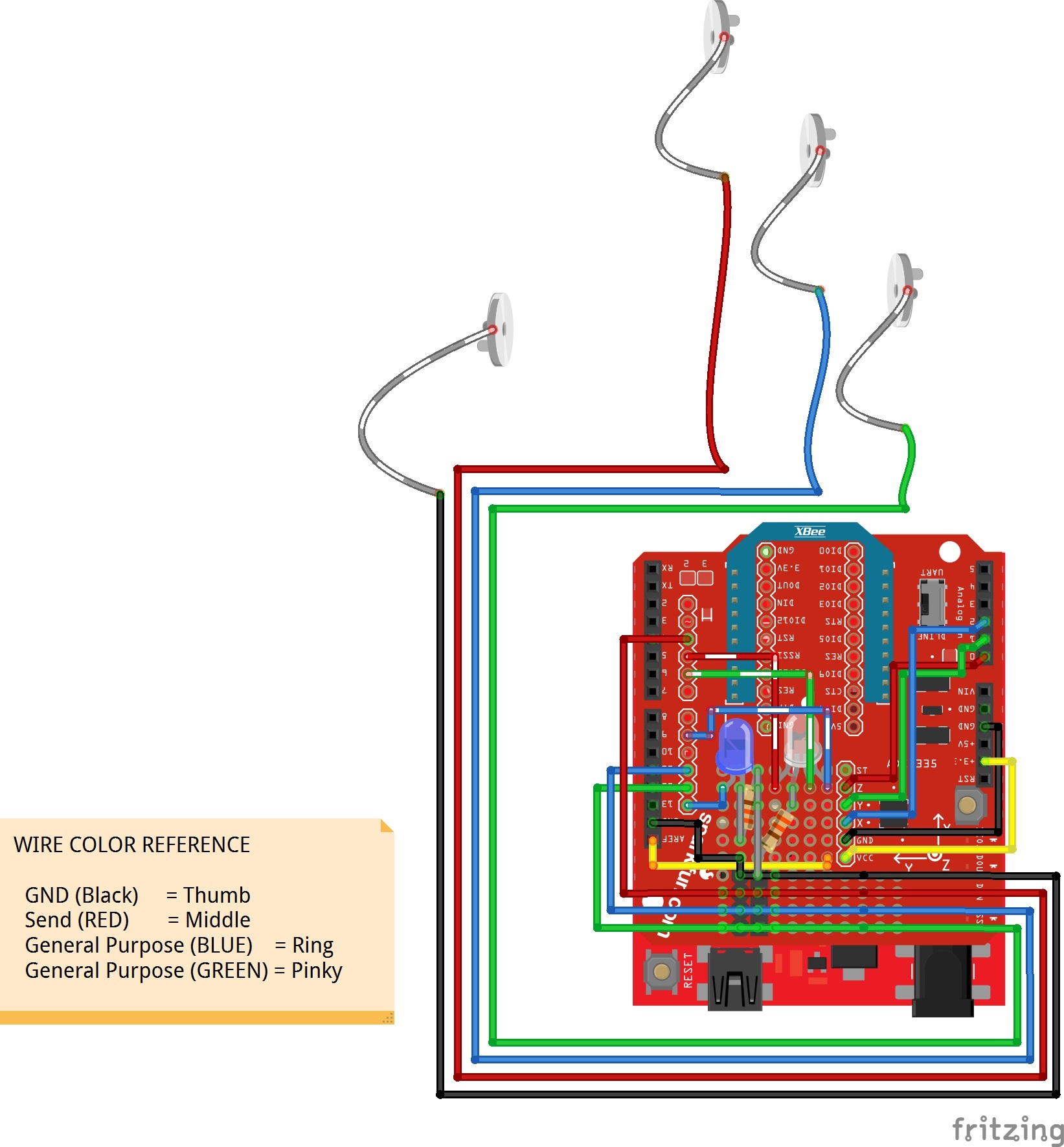
Analog Accelerometer
Since the ADXL335 requires 3.3V, we'll need to connect the VCC pin to 3.3V. To complete the connection for power, you will need to connect GND to GND. Then for the x, y, and z pins, you'll need to connect them to pin 2, 1, and 0, respectively.
Configuring AREF
Since the ADXL335 is 3.3V, we'll need to connect the Arduino's AREF pin to the 3.3V pin. This will configure the reference voltage used for the analog output from the accelerometer. As a result, we can measure smaller voltages (i.e. your 3.3V output) with the best resolution on a 5V Arduino.
Don’t use anything less than 0V or more than 5V for external reference voltage on the AREF pin! If you’re using an external reference on the AREF pin, you must set the analog reference to EXTERNAL before calling analogRead(). Otherwise, you will short together the active reference voltage (internally generated) and the AREF pin, possibly damaging the microcontroller on your Arduino board.
Assembled Shadow Chassis
We'll assume that you have a fully assembled robot with the Shadow Chassis.