Using the PSoC 6 Pioneer Board with the Pioneer IoT Add-on Shield
 SFUptownMaker
Hardware Overview
Let's go over the features of the Pioneer Kit IoT Add-on Board in detail.
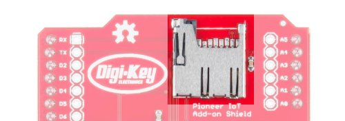
MicroSD Card Slot - The pins for this slot map to the SPI peripheral on most Arduino compatible boards, including the PSoC 6 BLE Pioneer Board.
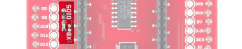
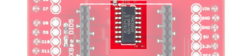
XBee Header - This header is spaced to accept the standard XBee footprint. It is compatible with all official XBee modules.
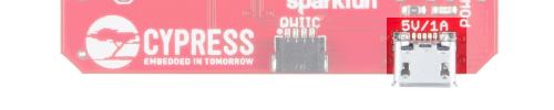
Qwiic Connector - This connector adds support for all of SparkFun's Qwiic modules. It supplies 3.3V.
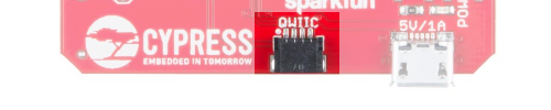
MicroB USB Power Connector - Data lines on this connector are not connected to anything. It provides 5V to the 3.3V regulator for the XBee module, overriding the 5V coming from the Arduino header and allowing high power XBee modules (such as the cellular, wifi, or Pro models) to function properly.
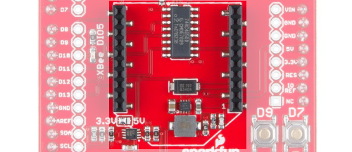
D7 and D9 Buttons - Two user buttons tied to pins D7 and D9 (P0.2 and P13.1 on the PSoC 6, or P1.0 and P0.4 on PSoC 4 BLE).
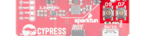
3.3V Regulator - Switch mode 3.3V power regulator capable of sourcing up to 1.5A, depending upon the upstream supply sourcing capacity. Draws power from 5V supply on Arduino pins or MicroB power connector. Supplies power to XBee header only.

Level Shift Buffer - Down converts from 5V signals to 3.3V signals. Allows board to be used in 3.3V or 5V systems.
I2C Level Shift Circuitry - Converts I2C signals from 3.3V to 5V, if necessary.
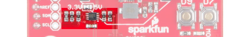
Voltage Supply Selection Jumper - Selects level to which I2C level shift circuitry translates. Default set to 3.3V. Set to 5V for use with 5V systems. Both the PSoC 4 and PSoC 6 Pioneer BLE boards are 3.3V systems.

XBee DIO5 LED - DIO5 defaults to some useful functions, especially on the WiFi module, where it shows connectivity to the configured WiFi network.