Using the PSoC 6 Pioneer Board with the Pioneer IoT Add-on Shield
 SFUptownMaker
Example: WiFi to Raspberry Pi Using the PSoC 6 Pioneer Kit
This example demonstrates how to send a signal to a Raspberry Pi via WiFi. It will show you how to access an XBee WiFi module, interprocess communication between the two cores of the PSoC 6, and how to receive and parse commands with a Raspberry Pi.
Following this example is going to require some setup, so let's walk through that now.
PSoC 6 Pioneer Kit Setup: Hardware
The Pioneer Kit side setup is trivial: insert the XBee WiFi module into the Pioneer IoT Add-on Shield and insert the shield into the Pioneer Kit Board's Arduino header.
The Raspberry Pi side requires more explanation. You'll need to setup both some hardware and some software on the Raspberry Pi.
PSoC 6 Pioneer Kit Setup: Software
The software project for the Pioneer Kit is available on GitHub.
Once you have downloaded and extracted the file somewhere, you can open the example (XBee_WiFi_Example) in PSoC Creator.
Before you do anything else, you need to open the "main_cm4.c" file and make a couple of changes. You'll find a section of code that looks like this:
language:c
char ssid[] = "your_ssid_here";
char rpi_ip[] = "raspi_ip_here";
char ssid_pw[] = "wifi_pw_here";
int dest_port = 5000;
char encrypt_mode = WPA2;
Hopefully, it's obvious what you need to do: change these settings to match your network setup. The encrypt_mode value can be WPA, WEP, WPA2, or (hopefully not!) NO_SECURITY. rpi_ip is a dotted quad (e.g., "10.8.253.193") that you can obtain from typing "ifconfig" in a command window on your Raspberry Pi (see below for instructions on opening a command window) and looking at the "wlan0" section.
To program the board, connect it to your PC via the included USB-A to USB-C cable. Then, click the "Program" button in the toolbar (as shown below) to automatically build the project and program the board.
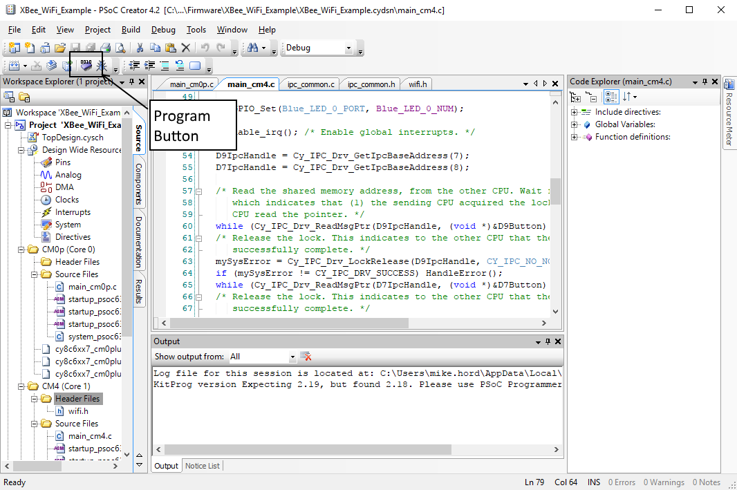
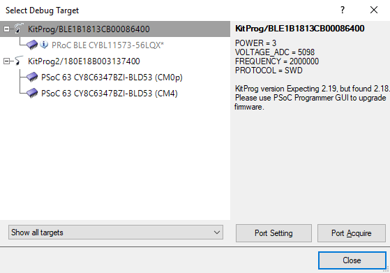
You may get a window as below asking you to choose a target to program. It does not matter which entry you choose under the "KitProg2" list item, either one will program the flash correctly.
Raspberry Pi Setup: Hardware
First, let's look at how the hardware is connected:
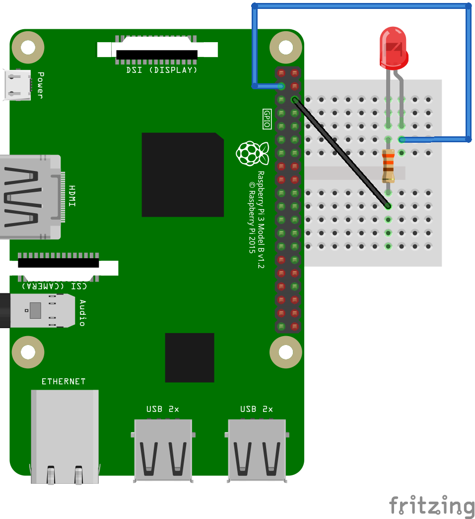
As you can see, we've connected an LED (with 330 ohm resistor) to pins 3 (GPIO 2) and 6 (ground) of the Raspberry Pi. This will allow us to toggle GPIO2 and see the result on the LED.
Raspberry Pi Setup: Software
We're going to assume that you have a Raspberry Pi set up with the latest version of Raspbian (the full install, not the lite version) running, and that it's connected to a keyboard, mouse, monitor, and local WiFi network. If this is not the case, please take a few moments to set this up. You can review our tutorial on setting up the Pi here.
Let's start from the desktop of the Raspberry Pi. You should have a screen up that looks something like this:

You'll need to click the little logo at the top of the screen (shown below) to open a command line. The rest of this tutorial will assume that you have that command line open.
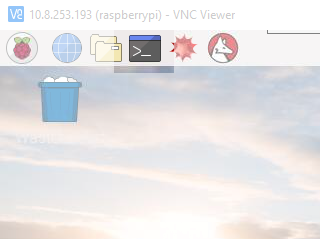
That will open a command line window. This allows you to tell the Raspberry Pi to directly execute commands.

We'll start by executing the command to install Flask. Flask is a web framework for Python that allows you to make a web front end that runs Python scripts on the sever backend fairly trivially. Type in the following command, then hit "Enter".
sudo pip install flask
A whole bunch of stuff will happen in the command line window and at the end of it, Flask will be installed on your Raspberry Pi.
The next step is to install the software that we've written to support this project from GitHub. The command for doing that is
git clone https://github.com/sparkfun/Flask_Tutorial
Again, you'll see some text scroll across the command line, and when the prompt returns, that'll be your indication that the install process is complete. Once that's complete, enter this command:
sudo python Flask_Tutorial/Python/app.py
That will launch the app and begin listening for input over TCP/IP from the Pioneer board. You should now be able to turn the LED connected to the Raspberry Pi on and off by pressing the D7 and D9 buttons on the IoT Shield. Neat!
So What's Going On Here? Pt. 1: The Pioneer Kit
Let's take a look at what exactly is happening, starting from a high level view of the PSoC 6 software project. Look at the Workspace Explorer frame on the left hand side of the screen. We'll walk through that frame, highlighting the files of importance and how they relate to the overall project.
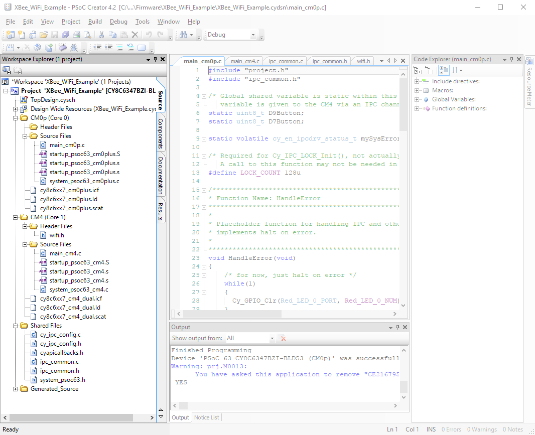
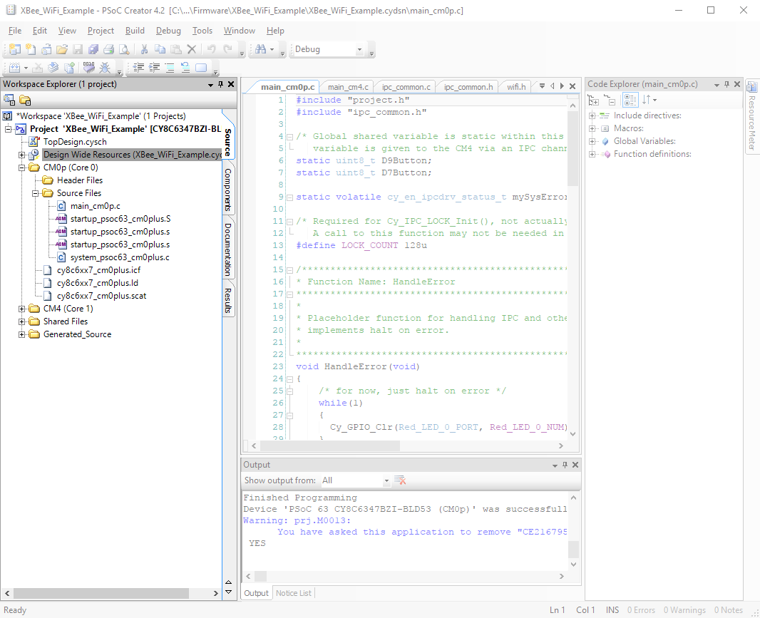
The top level of the project has six entries: the schematic ("TopDesign.sch"), the Design Wide Resources ("XBee_WiFi_Example.cydwr"), the source files associated with the Cortex-M0+ core ("CM0p (Core 0)"), the source files associated with the Cortex-M4 core ("CM4 (Core 1)"), files to be shared between the two ("Shared Files"), and support files generated by the IDE ("Generated_Source").
The schematic for this project is very simple, having a couple of LEDs, a couple of switches, and the UART used to transfer data to and from the XBee WiFi module. The LEDs are actually unused in the current implementation of the project.

We're going to skip over the contents of the .cydwr file. This file contains the pin assignments for the signals used in the schematic, the clock generation, and core configuration constants. If you want to investigate it more, feel free to dig in a little bit. Much of it should be self-explanatory.
Moving on down the list, we reach our Cortex-M0+ source files. You'll note that the top level in this subdomain has five entries: "Header Files", "Source Files", and three other files. We only need concern ourselves with the contents of the "Header Files" and "Source Files" subdomains, and in fact, only with one file in those: the "main_cm0p.c" file. This is where the main() function for the code which runs on the Cortex-M0+ processor lives.
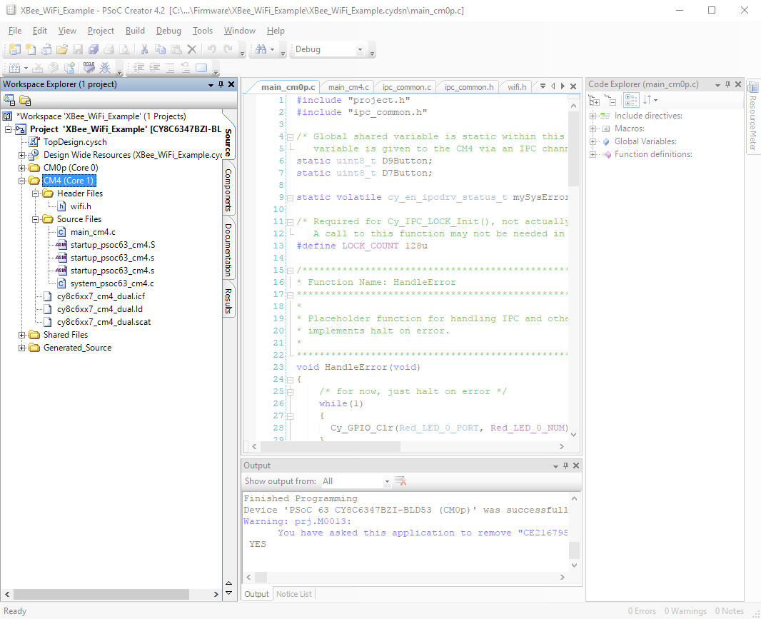
As you may have guessed from the structure of the workspace, there are two entirely separate codebases running for the two different cores. "main_cm0p.c" is the entry point for the Cortex-M0+ core's code, and then that core starts the Cortex-M4 core. There exists a similar subdomain for the Cortex-M4 core with similar files and again, we only need to worry about the "Header Files" and "Source Files" subdomains.
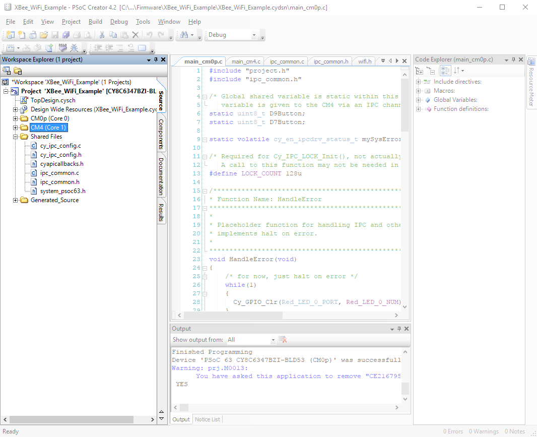
Finally, we have the "Shared Files" section. Most of these files are automatically generated, save the "ipc_common.c" and "ipc_common.h" files. These files are helpers for interprocess communication developed for this project.
The Cortex-M0+ Main File
Now that we've highlighted the important contents, let's take a look at the important bits of the code, one file at a time, starting with the "main_cm0p.c" file. This file handles all the activity that the Cortex-M0+ core does for the system: monitoring the two pushbuttons and sending a signal to the Cortex-M4 when one or the other of them is pressed.
However, this is not as straightforward as it seems, as the Cortex-M4 needs to be able to clear the signal once it has dealt with it, and that means multiple processes accessing the same data. Any time you have multiple processes working on the same dataset, you need to consider the effects of a write collision. What happens if one process attempts to change the data in the middle of the other process trying to change the same data? To deal with this we use a system protected reads and writes, set up in the "ipc_common" files.
To understand how this works, one must first understand the concept of an IPC channel. IPC channels use semaphores to write data from one process to another while guaranteeing that there will be no collision between the two core. At the beginning of application execution for each core you must establish endpoints for the IPC channels to be used during execution. Consider these two lines of code:
language:c
IPC_STRUCT_Type *D9IpcHandle;
D9IpcHandle = Cy_IPC_Drv_GetIpcBaseAddress(7);
The first creates a pointer for a struct which defines the characteristics of an IPC channel. The second actually sets that struct to point to a specific memory location, that of system IPC channel 7. We use channel 7 because channels 0-6 are reserved for system use.
Next we must, of course, tell the other core which memory address is associated with this IPC channel. That is what this function call does.
language:c
while(Cy_IPC_Drv_SendMsgPtr(D9IpcHandle, CY_IPC_NO_NOTIFICATION, &D9Button) != CY_IPC_DRV_SUCCESS);
D9Button is a variable set up earlier in the code. The function call is enclosed in a while() loop because we want to repeat the function call until we receive verification that the other process (i.e., the code running on the Cortex-M4 core) has received this information. We also want to wait until the lock on the variable is released, indicating that the Cortex-M4 has finished reading the pointer value.
language:c
while(Cy_IPC_Drv_IsLockAcquired(D9IpcHandle));
Finally, we drop into our infinite loop for the application, where the custom functions ReadSharedVar() and WriteSharedVar() handle updating the shared variables which communicate button status with the other core. We'll delve into those functions later.
The Cortex-M4 Main File
In the Cortex-M4 main() function, we repeat some of the same operations as we did in the Cortex-M0+ main() function vis-a-vis setting up of the IPC channel.
language:c
IPC_STRUCT_Type *D9IpcHandle;
D9IpcHandle = Cy_IPC_Drv_GetIpcBaseAddress(7);
Once that's completed we must then call some code to "catch" the message that was sent from the Cortex-M0+ process, containing the address of the shared variable to be accessed.
language:c
while (Cy_IPC_Drv_ReadMsgPtr(D9IpcHandle, (void *)&D9Button) != CY_IPC_DRV_SUCCESS);
Again, we enclose this call in a while() loop so that it gets continually called until the message is sent from the Cortex-M0+. Then we must release the lock on that IPC channel so that the Cortex-M0+ process knows that it can continue operation and use the IPC channel in the future. There is no need to enclose this in a while() loop because it is open ended: the call only needs to be issued once to release the lock, versus checking that the lock has been released, which must be repeated until such time as the lock is released.
language:c
Cy_IPC_Drv_LockRelease(D9IpcHandle, CY_IPC_NO_NOTIFICATION);
Once all of this has been completed, we must set up the XBee WiFi shield to access our local network. We won't duplicate all that code here, as it's well documented in the example.
In the infinite loop that runs the application code, we again call the custom functions ReadSharedVar() and WriteSharedVar() to access the variables holding the button status, which are shared with the Cortex-M0+ core. Let's take a closer look at what these functions do.
The "ipc_common.c" File
As mentioned earlier, we must use a semaphore protected variable to communicate between the two processes currently running on the PSoC6. By protecting our reads and writes with a semaphore we ensure that there will be no collisions of access to those variables.
We'll look at the WriteSharedVar() function first. It accepts as parameters a pointer to a shared variable, a value to be written into that shared variable, and a semaphore number to use for protecting this transaction. It is important that both processes use the same semaphore to protect any variable which is written this way; in "ipc_common.h" there is a define for semaphores to be used for each of the two variables to be shared between the processes. There are 128 semaphores available to the application, but the semaphores 0-15 are used behind the scenes, so user semaphores must be number 16 or higher.
This first section of code handles setting the semaphore. It is set to timeout in 1000 microseconds. This is important because we don't want to idle excessively waiting for the other process to release the semaphore.
language:c
for (timeout = 0ul; timeout < MY_TIMEOUT; timeout++)
{
    rtnVal = (uint32_t)Cy_IPC_Sema_Set(semaID, false);
    /* exit the timeout wait if semaphore successfully set or error */
    if ((rtnVal == (uint32_t)CY_IPC_SEMA_SUCCESS) || IsSemaError(rtnVal))
    {
        break;
    }
    CyDelayUs(1);
}
if (timeout >= MY_TIMEOUT) rtnVal = CY_RET_TIMEOUT;
This second section of code handles writing the shared variable and releasing the semaphore. Again, clearing the semaphore is done within a timeout loop.
language:c
if (rtnVal == CY_IPC_SEMA_SUCCESS)
{
    *sharedVar = value;

    /* timeout wait to clear semaphore */
    for (timeout = 0ul; timeout < MY_TIMEOUT; timeout++)
    {
        rtnVal = (uint32_t)Cy_IPC_Sema_Clear(semaID, false);
        /* exit the timeout wait if semaphore successfully cleared or error */
        if ((rtnVal == (uint32_t)CY_IPC_SEMA_SUCCESS) || IsSemaError(rtnVal))
        {
            break;
        }
        CyDelayUs(1);
    }
    if (timeout >= MY_TIMEOUT) rtnVal = CY_RET_TIMEOUT;
}
Now let's look at the ReadSharedVariable() function. In this case, we're passing a const pointer to the variable, a pointer to the copy, and the semaphore number. The code is identical to the WriteSharedVariable() function except for the actual access to the variable:
language:c
*copy = *sharedVar;
As you can see, this time we're setting our copy to the value of the shared variable. Not surprising considering the point of this function is to move the shared variable into a local copy for the process to work on!
What's Going on Pt. 2: The Raspberry Pi
Let's look at the code on the Raspberry Pi. It's pretty simple!
language:python
from flask import Flask
import RPi.GPIO as GPIO
These are your general import statements. We installed Flask earlier, and the RPi.GPIO module comes installed on the Raspberry Pi already. Next we get into setting up our GPIO:
language:python
GPIO.setmode(GPIO.BCM)  # Sets up the RPi lib to use the Broadcom pin mappings
                        #  for the pin names. This corresponds to the pin names
                        #  given in most documentation of the Pi header
GPIO.setwarnings(False) # Turn off warnings that may crop up if you have the
                        #  GPIO pins exported for use via command line
GPIO.setup(2, GPIO.OUT) # Set GPIO2 as an output
This section should be fairly understandable via the comments. Then we have to set up our Flask app:
language:python
app = Flask(__name__)   # Create an instance of flask called "app"
We'll now refer back to that Flask app for our route handling functions. Flask behaves a lot like a standard webserver, serving up pages in response to http requests against a certain path, except instead of serving a page it executes a chunk of python code. The default route handler (i.e., when no route is given in the http request) is thus:
language:python
@app.route("/")         # This is our default handler, if no path is given
def index():
    return "hello"
The result, should you visit this in a web browser, is a simple page reading "hello" in plain text. The real magic happens when you visit a more highly defined path:
language:python
@app.route('/gpio/<string:id>/<string:level>')
def setPinLevel(id, level):
    GPIO.output(int(id), int(level))
    return "OK"
In this case, when you send the path "/gpio/2/1", the Flask app interprets that to be a GPIO number (we've only enabled GPIO 2) followed by a level to set the GPIO to (1 or 0). The last thing we need to do is provide the system with some insight into how to run the app:
language:python
if __name__ == "__main__":
    app.run(host='0.0.0.0', port=5000)
This code specifies that the app should be run locally, visible to the outside world, on port 5000. I recommend leaving it as it is, but you can change the port number if you really want to (and really know what you're doing).