Touch Potentiometer Hookup Guide
 Joel_E_B
Example 3: Interfacing with Microcontrollers
The first two examples showed how you can use the Touch Pot right out of the box, no programming necessary. This example will show you how to connect the Touch Pot to a microcontroller. It will also cover how to add more than one Touch Pot to an I2C bus. For an example of interfacing the Touch Pot to a computer over serial, visit the User Manual
Hardware Hookup
This example uses a Pro Micro 5V to communicate with the Touch Pot over I2C. The connections between the two are as follows:
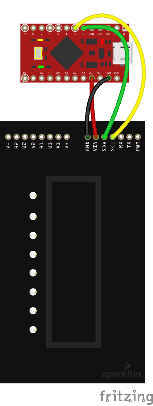
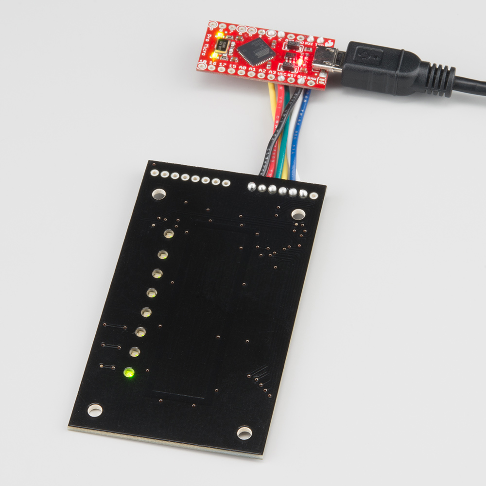
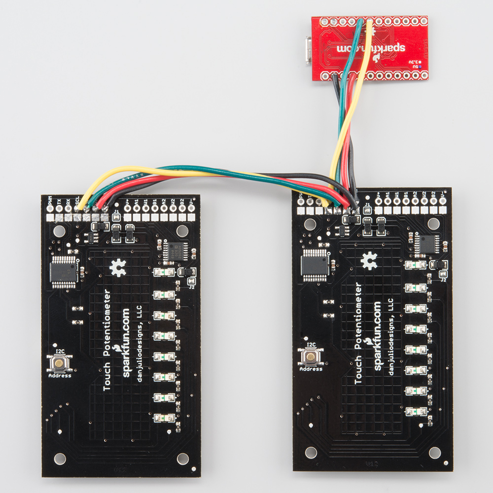
You should end up with something that looks like this:
If you have not used a Pro Micro before, you should visit the Hookup Guide. In particular, you'll need to install some additional drivers and add the board definitions for the Pro Micro to the Arduino IDE. The Hookup guide covers this for both Windows and Mac and Linux users. Alternatively, you could use any microcontroller that has I2C and Serial communications.
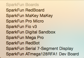
Once the Pro Micro is setup in the Arduino IDE, select the correct board (Pro Micro) and serial port.
Then, upload the following code to the Pro Micro:
language:c
/*
 * Simple Touch Potentiometer Example with Arduino
 *
 * Reads the pot value and controls the brightness of the Arduino LED on
 * Digital Pin 13.  Also logs new values to the serial port.  Utilizes
 * both the direct and indirect command interface forms.
 *
 * Assumes Touch Pot is at I2C Address 8
 *
 * Released into the public domain by Dan Julio.  This software is supplied on an as-is
 * basis and no warranty as to its suitability for any particular purpose is either made
 * or implied.  danjuliodesigns, LLC. will not accept any claim for damages howsoever
 * arising as a result of use or failure of this software.
 */
#include "Wire.h"

int i2cAddr = 8; // Direct access at i2cAddr, indirect registers at i2cAddr+1

uint8_t prevValue;
uint8_t curValue;

void setup() {
  Serial.begin(115200);
  Wire.begin();
  pinMode(13, OUTPUT);

  // Demonstrate access to Touch Potentiometer registers
  WriteTpReg(1, 128); // set to 50% by writing to register 1
  curValue = ReadTpReg(1); // read back value just set

  // Set Arduino LED PWM to match
  analogWrite(13, curValue);
  prevValue = curValue;
}

void loop() {
  delay(50);  // Read ~20 times/second

  // Demonstrate direct access to Touch Potentiometer value
  curValue = ReadTpValue(); // faster I2C access than register read
  if (curValue != prevValue) {
    analogWrite(13, curValue);
    Serial.println(curValue);
    prevValue = curValue;
  }
}

// Write a Touch Potentiometer register
void WriteTpReg(uint8_t addr, uint8_t data) {
  Wire.beginTransmission(i2cAddr+1);
  Wire.write('W');
  Wire.write(addr);
  Wire.write(data);
  Wire.endTransmission();
}

// Get the Touch Potentiometer value
uint8_t ReadTpValue() {
  Wire.requestFrom(i2cAddr, 1);
  if (Wire.available()) {
    return Wire.read();
  } else {
    return 0;
  }
}

// Read a Touch Potentiometer register
uint8_t ReadTpReg(uint8_t addr) {
  Wire.beginTransmission(i2cAddr+1);
  Wire.write('R');
  Wire.write(addr);
  Wire.endTransmission();

  Wire.requestFrom(i2cAddr+1, 1);
  if (Wire.available()) {
    return Wire.read();
  } else {
    return 0;
  }
}
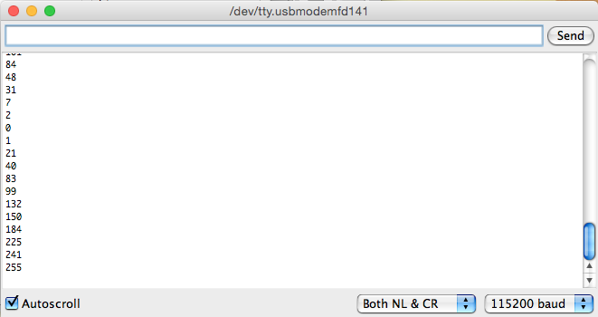
Once that is uploaded, open your favorite Serial Terminal at 115200 baud. As you slide your finger along the capacitive touch strip ion the Touch Pot, you should see the current PWM value print out on the terminal.
Multiple Touch Potentiometers
Building on this same example, we can add a second Touch Pot to the I2C bus. You can use the SMD pads found on the back of the Touch Pot to solder a second Touch Pot to the first.
In order for this to work, you'll need to change the I2C address on one of the Touch Pots. This can be accomplished through the TP Utility app, or it can be changed on the fly by pressing the button on the back of the Touch Pot three times.
You will see the all the LEDs on the Touch Pot blink three times, indicating you are in address change mode. As you slide your finger along the sensor, the LEDs will change. They are telling you the address in binary. Holding the Touch Pot sideways, with the PTH holes on the left, you will see every combination of numbers between 0b01 and 0b64.
You can repeat this process adding up to 64 Touch Pots on a single I2C bus.
More information on interfacing to microcontrollers through the I2C port can be found in the User Manual.