Touch Potentiometer Hookup Guide
 Joel_E_B
Example 1: PWM Lighting Controller
This example will demonstrate how to use the PWM output on the Touch Potentiometer to control an LED lighting system.
Many LED lighting systems use constant current power supplies, such as our PicoBuck and FemtoBuck LED Drivers. These drivers usually have a PWM input, allowing you to fade the LEDs on or off. The best part: there is no programming necessary.
Hardware Hookup
Before making any connections, you'll need to decide how you want your lighting system to behave. The PicoBuck has three, independently-controlled channels capable of handling PWM signals, whereas the FemtoBuck has only one channel and one PWM input. For this example, all three inputs on a PicoBuck were tied together so that all three channels would fade in unison. You can leave each channel separate, which is great for RGB color blending systems, but you'll need a Touch Pot for each individual channel in that scenario or a way to switch between channels.
The Touch Pot works best as a lighting dimmer control when the PWM output set to Non-linear. This can be accomplished in the tputil app mentioned in the previous section.
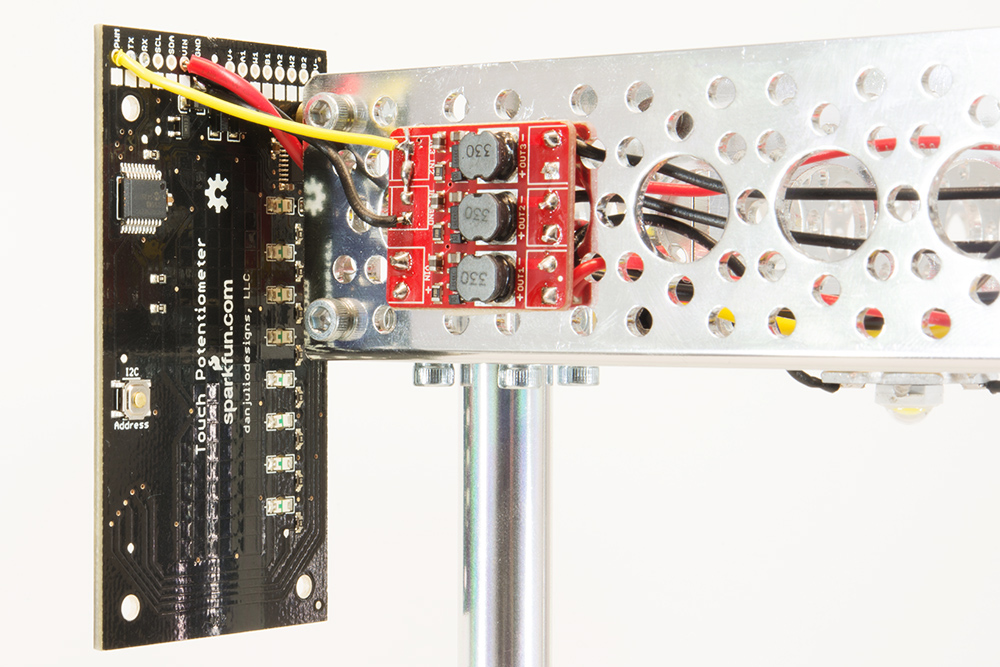
Connecting the Touch Pot to the PicoBuck only requires two wires. Ground needs to connect to ground on the opposite board. The PWM output pin on the Touch Pot connects to the three input pins on the PicoBuck (IN1, IN2, and IN3) that are tied together, as mentioned above.
Here is a wiring diagram showing how this would look with a FemtoBuck. The same would apply to the PicoBuck; just tie the three PWM pins together.
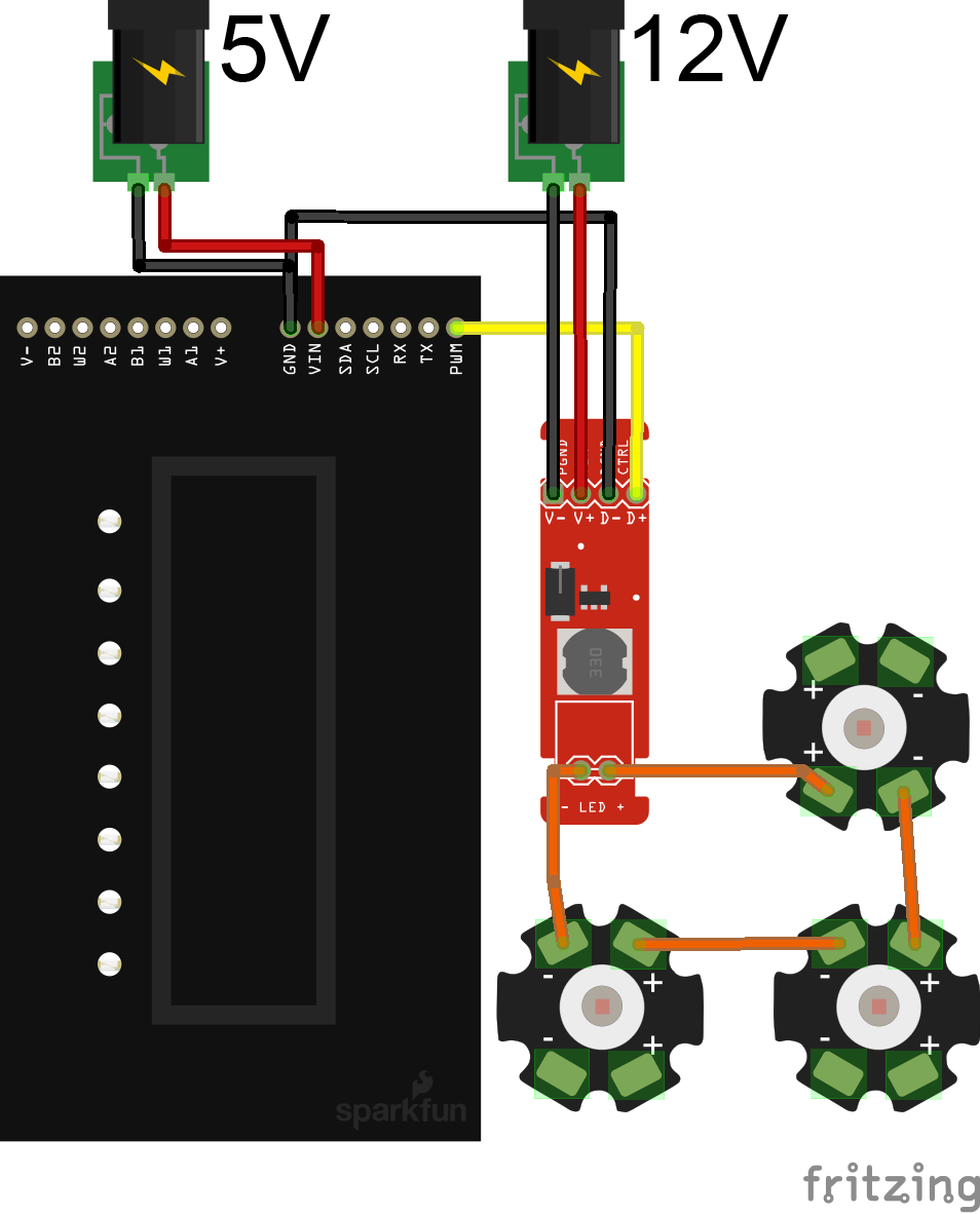
Last, you'll need to power both the Touch Pot and the Constant Current Driver. The Driver will accept voltages up to 36V, but 12V will be more common. You will also need to power the Touch Pot with 5V. You can use two separate power supplies, such as a 5V and 12V wall adapter, or you can find a dual-voltage supply. We offer a 12V/5V power supply (TOL-15664). For a more robust lighting system, you can also get a decent power supply such as a Meanwell. Just make sure to connect the circuit appropriate voltages.
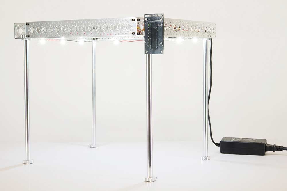
Once everything is connected, you should be able to apply power to the Touch Pot and the LED Driver. Everything should power on, and the Touch Pot should start in the 'off' position. Run your finger along the capacitive touch strip, and watch the LEDs fade on and off.
You can read more about the PWM capabilities of the Touch Pot in the user manual on page 15.