Touch Potentiometer Hookup Guide
 Joel_E_B
Board Overview
There are several different ways to interface to the Touch Potentiometer. This section will briefly cover each of these methods. Most of this information can be found in the user manual.
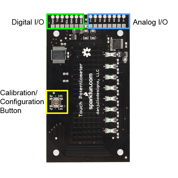
Digital I/O
The Touch Potentiometer Digital IO connections consist of the VIN and Ground power signals for the micro-controller and digital portion of the AD5262, a TTL-level serial interface, an I2C interface, and the PWM output. The Touch Potentiometer communicates to a host device using TTL-level serial interface or an I2C interface. Both interfaces are active simultaneously. The serial interface operates at 9600 baud. The I2C interfaces is a 7-bit slave with a maximum clock rate of 100 kHz. It does not support General Call or 10-bit addressing.
| Pin Label | Function |
|---|---|
| GND | Ground |
| VIN | +5-12 Volt power input |
| SDA | I2C SDA (Data) |
| SCL | I2C SCL (Clock) |
| RX | Serial TTL RX Input |
| TX | Serial TTL TX Output |
| PWM | Pulse-width Modulation Output |
Power
The Touch Pot has a 5V LDO voltage regulator (Vreg) to allow the board to be powered from external sources that are larger than 5V (great for lighting and audio systems that require 9-12V). The VIN pin can be powered with any voltage between 4.6-12V. The datasheet for the Vreg can be found here.
The capacitive sensors may be adversely affected by electrical noise. They are sensitive to 50 and 60-Hz energy that may be coupled through power supplies with inadequate line filtering or configurations with a ground loop (for example, a system that has a DC power supply and is also connected to a computer with its own power supply). It may be necessary to include an AC line filter in front of some cheap switch-mode power supplies to eliminate ground loop conditions.
Serial Communication
A computer with a USB interface and terminal emulator program can access the Touch Potentiometer using the serial interface connected to a USB-to-serial device like a FTDI Basic Breakout Board or a micro-controller like the 5V Pro Micro that has both a USB interface with Communications Device Class (CDC) support and a serial port. The Touch Potentiometer serial interface operates at 5V logic levels with a data rate of 9600 baud, eight data bits, no parity and one stop bit (8N1).
I2C Communication
The Touch Pot communicates over I2C just as any other I2C sensor would. It supports 7-bit addressing and a maximum transfer rate of 100 kHz. It may be connected to a 5V Arduino I2C peripheral (A4/A5) directly. Level translators should be used for 3.3V Arduino boards (or other 3.3V micro-controllers). The Touch Potentiometer activates weak pull-ups on its I2C signals, so pull-up resistors are not necessary for short connections (a few inches). Pull-up resistor values of 4.7kΩ to 10kΩ may be used.
The default I2C address is 0x08. There are 64 available I2C addresses. The Touch Pot uses two consecutive I2C addresses, which is why only 64 are available. Details on changing that address in the utility app and on the fly will discussed later in the tutorial.
Pulse-width Modulation
The PWM output generates a signal with a duty-cycle that is proportional to the current Touch Potentiometer value. A value of zero results in a PWM output of 0% duty cycle (off). A value of 255 (full-scale) results in a PWM output of nearly 100% duty cycle (on).
Analog I/O
The Touch Potentiometer Analog IO signals consist of the [AD5262] wiper and wiper power supply signals. The AD5262 supports two separate digital 20kΩ potentiometers, each with two terminals and a wiper connection. They have their own power supply connections allowing the voltage levels on the potentiometers to exceed the +5 volt logic power supply (see important note below).
| Pin Label | Function |
|---|---|
| A1, A2 | A Terminals for potentiometer 1 and 2 |
| W1, W2 | Wiper Terminals for potentiometer 1 and 2 |
| B1, B2 | B Terminals for potentiometer 1 and 2 |
| V+ | Positive Power Supply. Connected at the factory to the 5V logic signal by jumper J1. With J1 removed this may be connected to a positive voltage up to 15V. Note the sum of |V-| + |V+| must be 15V or less. |
| V- | Negative Power Supply. Connected at the factory to ground by jumper J2. With J2 removed this may be connected to a negative voltage down to -5V. Note the sum of |V-| + |V+| must be 15V or less. |
Care must be taken with V+ and V- to prevent damage to the ICs on the Touch Potentiometer.
1. V+ and V- must always be connected to power and should be powered before or at the same time voltages appear on the A, B and W signals and 5V input.
2. By default, V+ is connected to 5V with jumper J1 and V- is connected to ground with jumper J2. Voltages on the A, B and W signals should not exceed the range of 0 - 5V with these jumpers installed. Remove these jumpers by removing the solder blob if a different power supply will be connected to V+ and/or V-.
3. The maximum voltage potential between V- and V+ is 15 volts. V- maximum is -5V. V+ maximum is 15V.
4. Electrical noise on V- and V+ may be coupled into the signal passing through the potentiometer. A power supply connected to V- and V+ may require additional filtering to eliminate this noise.
Calibration/Configuration Button
The Touch Pot has a button located on the backside that allows the user to change both the I2C address on the fly as well as calibrate the capacitive touch sensor on the fly. As indicated by the silkscreen near the button, three rapid, successive presses will enter I2C address change mode, and four presses will start the calibration process. The presses have to be complete within 2 seconds, or they are ignored