Thing Plus Dual-Port Logging Shield Hookup Guide
 PaulZC
Hardware Overview
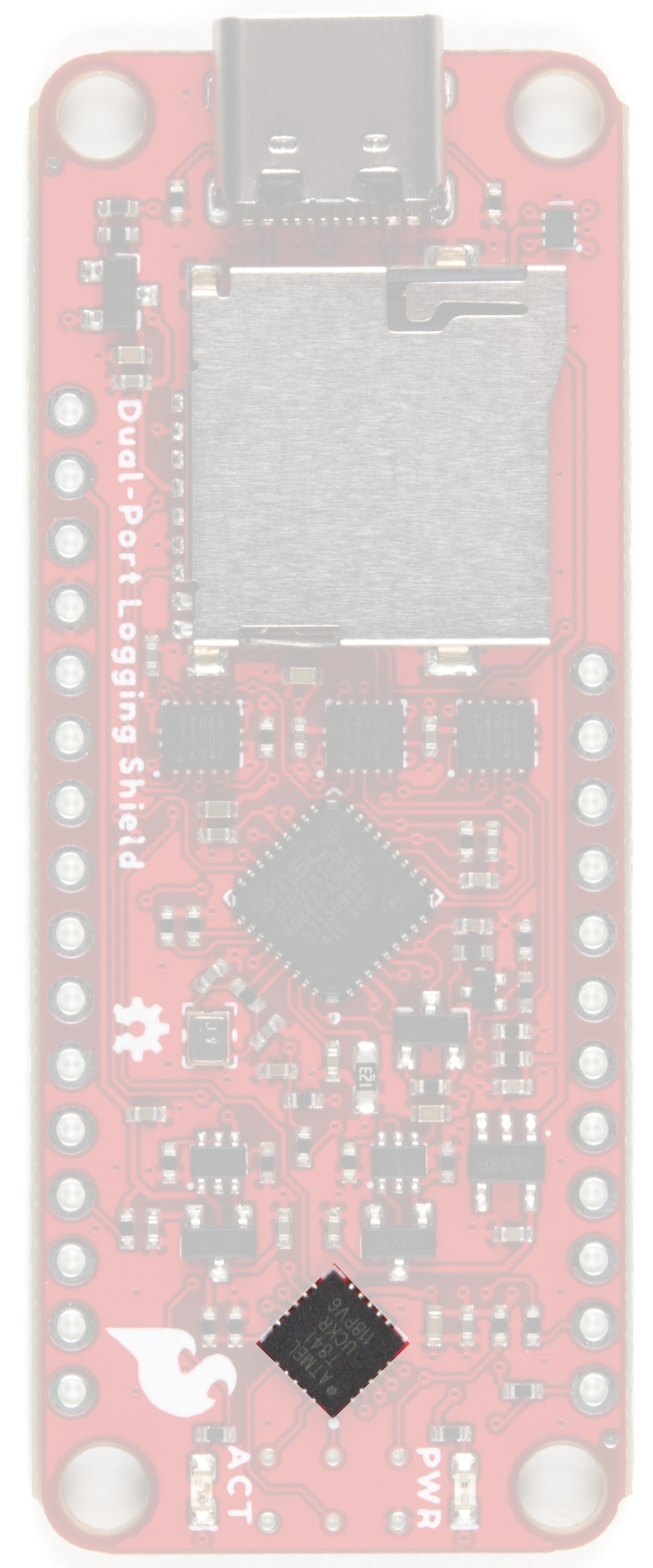
ATtiny841
The Dual-Port Logging Shield has an ATtiny841 microcontroller on it to act as an arbiter:
- If you power up your Thing Plus, the ATtiny841 will automatically put the Dual-Port Logging Shield into SPI mode, so your Arduino code can access the microSD card as normal
- If you power the Shield from your computer by connecting it via USB-C, the ATtiny841 will put the Shield into SDIO "thumb drive" mode. Your computer can then read and write data really quickly!
- If you have both your Thing Plus powered up - and have your computer connected - then you can switch between the two modes by giving the ATtiny841 some very simple commands over I2C!
You can configure the ATtiny to automatically default to SPI mode or SDIO "thumb drive" mode if both power sources are powered up simultaneously. It's your choice!
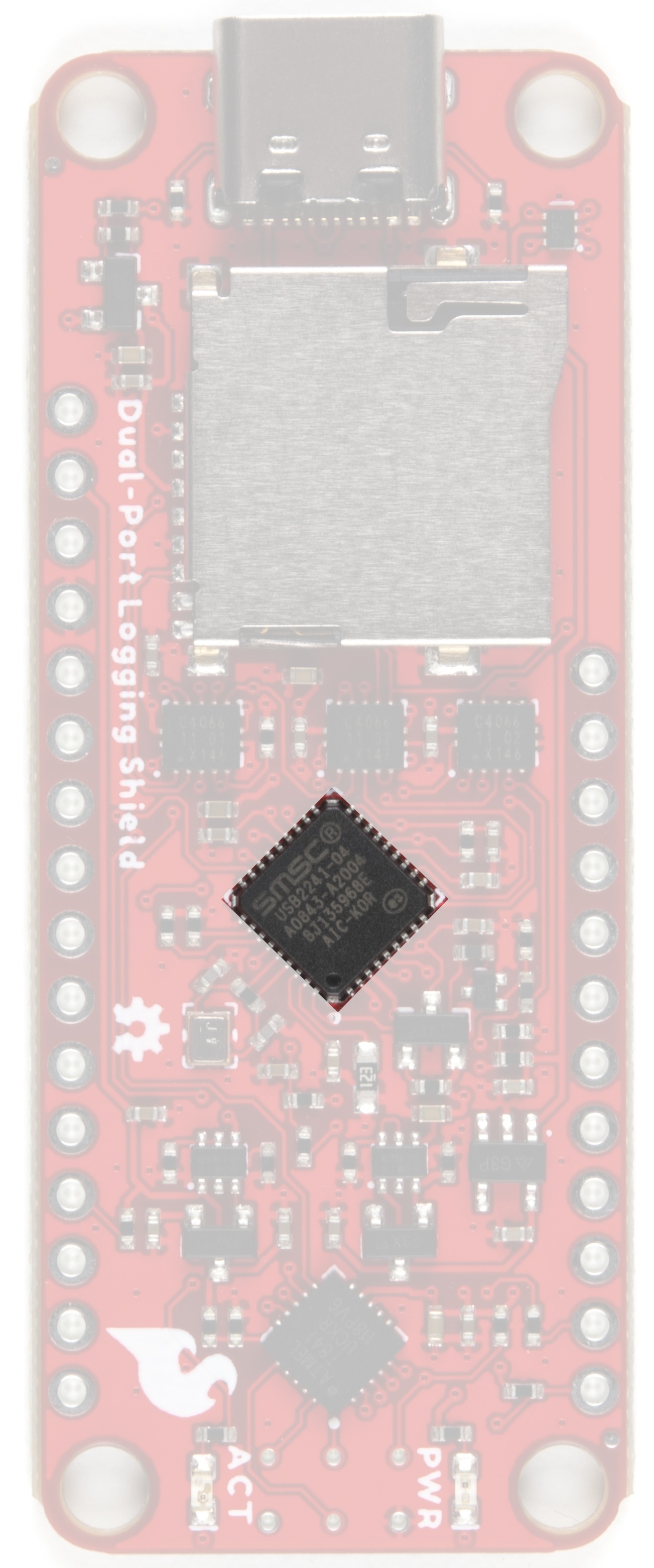
USB2241
The USB224x is a fully integrated, single chip solution capable of ultra high performance operation. Average sustained transfer rates exceeding 35 MB/s are possible if the media and host can support those rates. The USB224 includes provisions to read/write secure media formats.
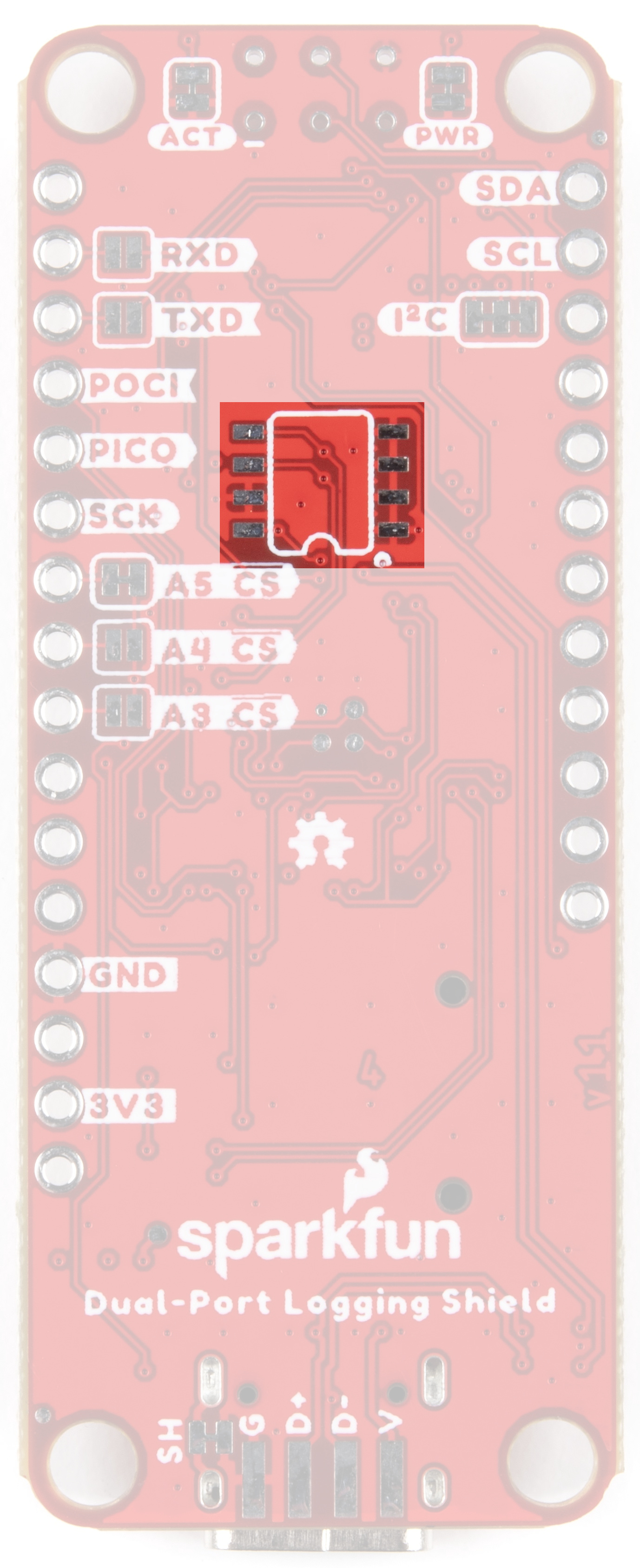
Programming Footprint
Advanced users can change the shield's USB Vendor ID (VID), Product ID (PID), Manufacturer Name etc. by adding an optional 24C04 (512x8) EEPROM and configuring it with Microchip's USBDM tool.
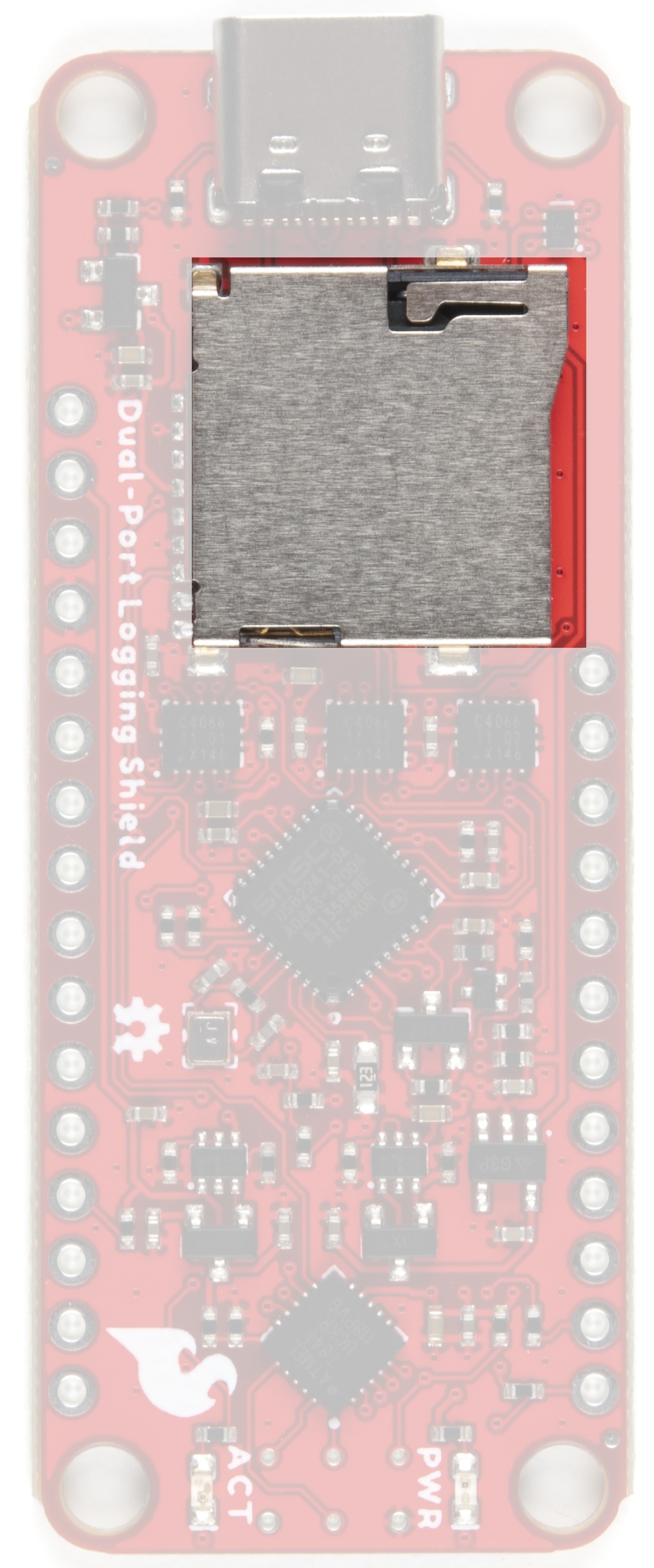
microSD Card Slot
The USB2241, which provides the USB interface, supports FAT32, exFAT and NTFS on cards up to and including 32GB. Cards larger than 32GB are not supported.
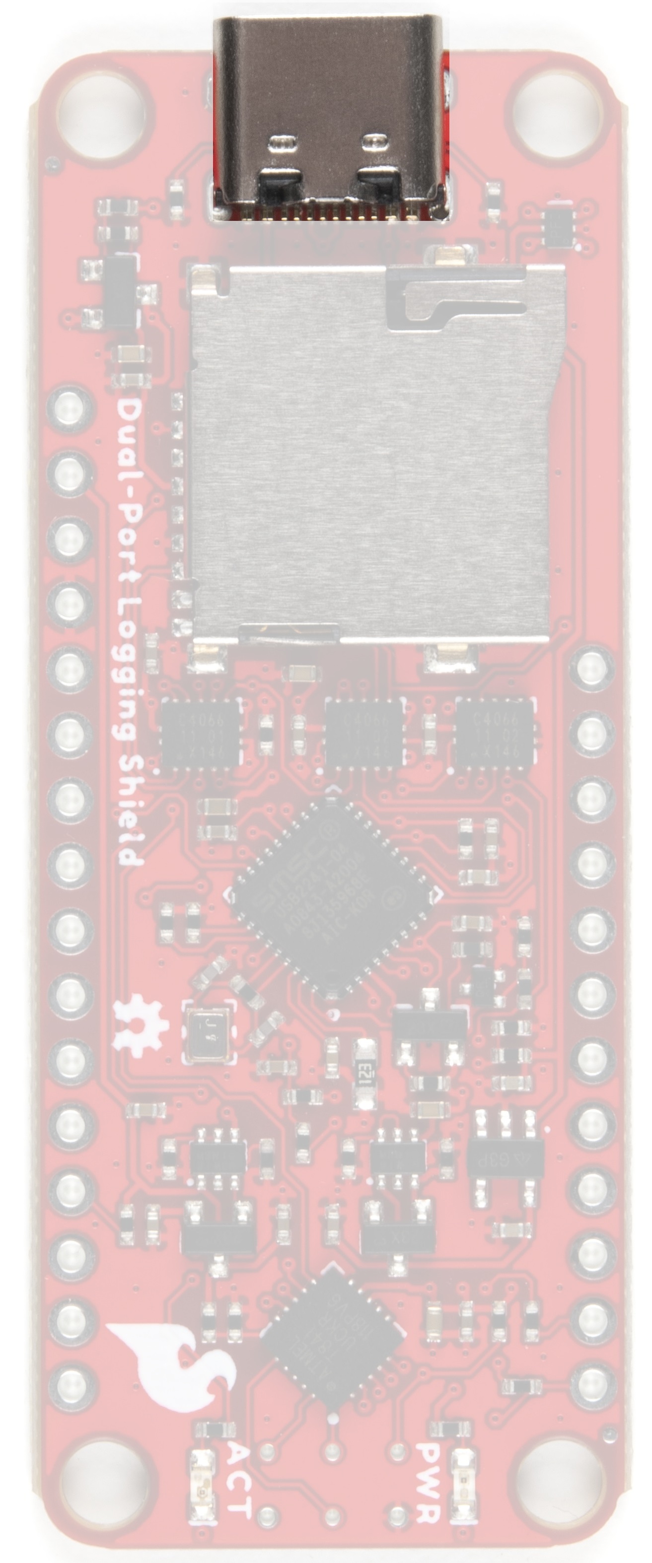
USB-C
While attached to the Thing Plus, you can log data to and read data from your microSD card over SPI as usual. But you can also connect the shield directly to your computer via the USB-C port and read/write files directly.
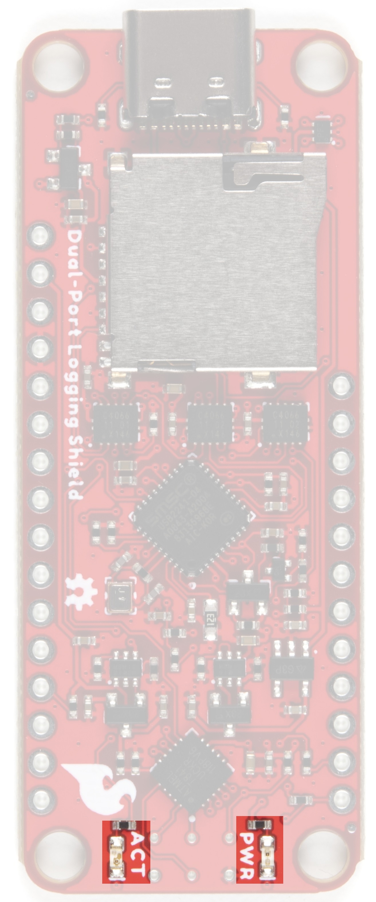
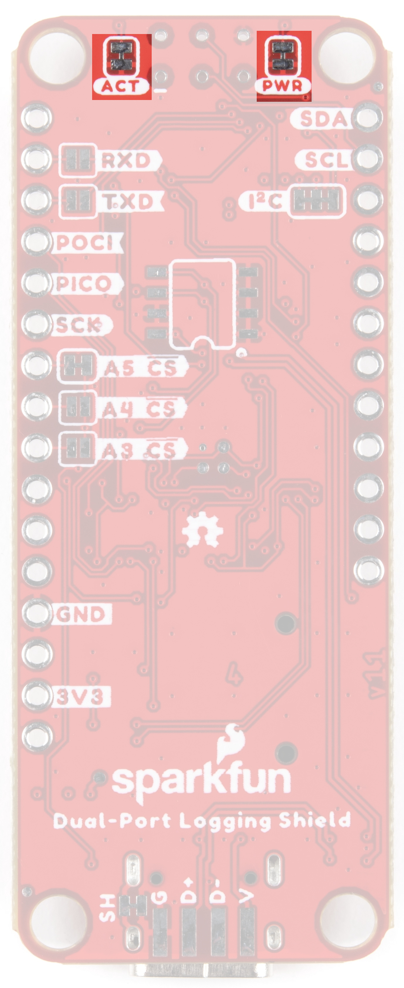
LEDs
There are two LEDs on the front of the board; PWR and ACT. PWR should be self-explanatory - it is the LED that lights up when there is power to the shield. ACT stands for activity monitor - this shows data movement on the shield in SDIO "thumb drive" mode.
Jumpers
I2C
These split pads are closed by default to enable the shield's I2C pull-up resistors. Please be aware that, with the pull-ups enabled, the shield's VCC will try to back-feed power to the Thing Plus through the pull-ups on both boards. Opening the jumpers will prevent this.
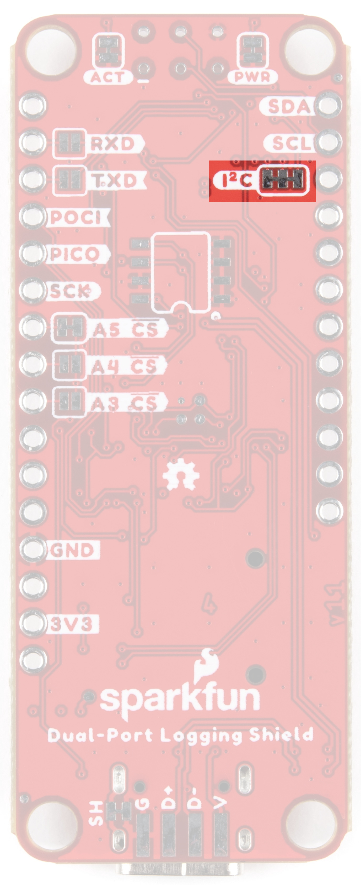
The default (unshifted) I2C address is 0x51 but is programmable via the code.
LEDS
Should you wish to disable either of the LEDs on the front of the board, cut the trace on the appropriate jumper.
Chip Select
By default, the microSD SPI chip select signal is connected to pin A5 on the Thing Plus. If you are already using that pin for something else, you can open the A5 jumper and close A4 or A3 instead.

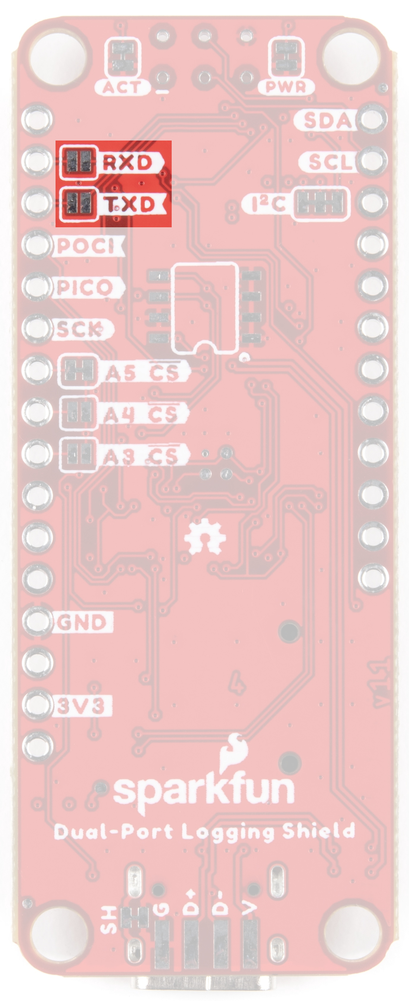
Serial
The ATtiny841 has a Serial (UART) interface but we only make limited use of it in the standard shield firmware. If you want to, you can connect the ATtiny serial pins to the standard Thing Plus Serial pins by closing the RXD and TXD jumpers. You will then see some diagnostic messages at 9600 baud when the ATtiny powers up. These jumpers are really there for any advanced users who want to write their own firmware for the ATtiny!
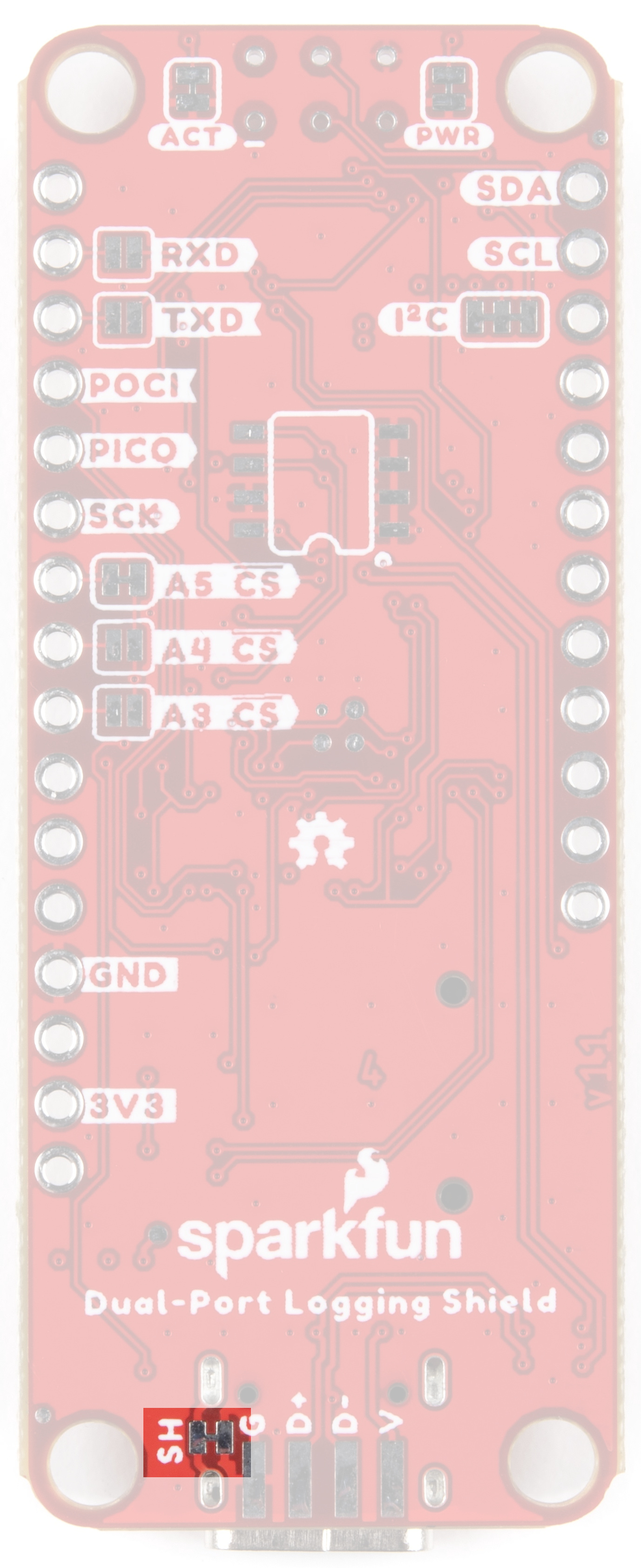
SH
By default, the USB-C shield is connected to the shield GND (0V). You can isolate the shield if you want to by opening the SH jumper.
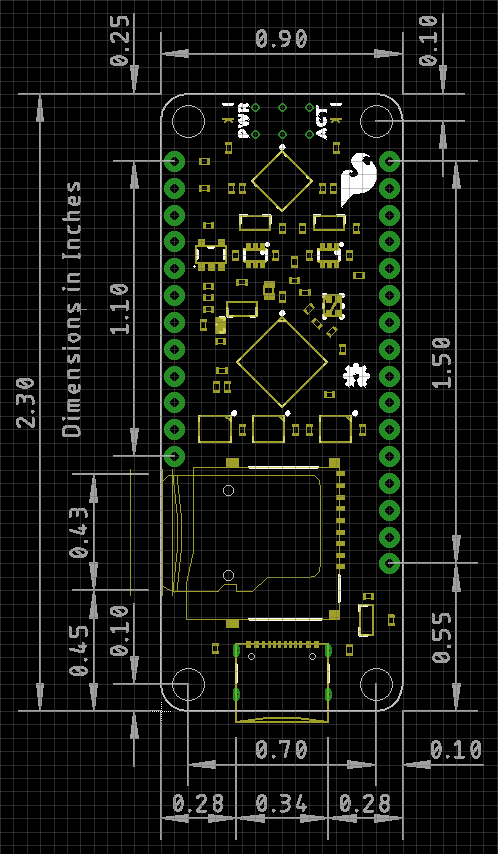
Board Outline