SX1509 I/O Expander Breakout Hookup Guide
 jimblom
Example: Digital In/Out and PWM
As with almost any I/O expander, each of the SX1509's GPIO can be configured as simple digital inputs or outputs. So you can toggle LEDs on or off, monitor for button presses, or even bit-bang more advanced digital interfaces like SPI (probably nothing that's timing-dependent though).
Here's a quick example that shows how you can digitalWrite or digitalRead using the SX1509. If you want to follow along, hook up a circuit like below:
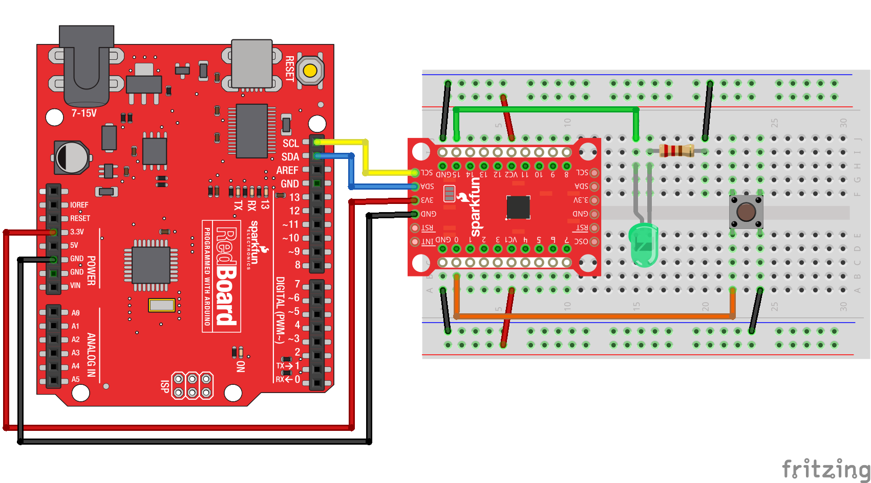
Match up 3.3V, GND, SDA, and SCL between your Arduino and the SX1509 Breakout. Then connect an LED to I/O 15 -- you can either configure it to source or sink current. And connect an active-low button to I/O 0.
Then throw this code onto your Arduino:
language:c
/*************************************************************
digitalReadWrite_Combined.ino
SparkFun SX1509 I/O Expander Example: digital I/O (digitalRead/digitalWrite)
Jim Lindblom @ SparkFun Electronics
Original Creation Date: September 21, 2015
https://github.com/sparkfun/SparkFun_SX1509_Arduino_Library
This example demonstrates the SX1509's digitalRead and digitalWrite
functionality. We'll attach an active-low button to an
INPUT_PULLUP input and attach an LED to a pin set as an OUTPUT.
Then whenever the button read's LOW, we'll toggle the LED.
Note that the code will wait until the button is released
before reading the SX1509 pins again.
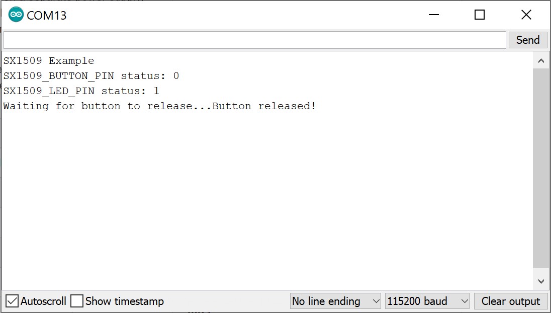
After uploading the sketch, open your serial monitor and set
it to 115200 baud.
Hardware Hookup:
SX1509 Breakout ------ Arduino -------- Breadboard
GND -------------- GND
3V3 -------------- 3.3V
SDA ------------ SDA (A4)
SCL ------------ SCL (A5)
0 ---------------------------------]BTN[----GND
15 -------------------------------- LED+
LED- -/\/\/\- GND
330
Development environment specifics:
IDE: Arduino 1.6.5
Hardware Platform: Arduino Uno
SX1509 Breakout Version: v2.0
This code is beerware; if you see me (or any other SparkFun
employee) at the local, and you've found our code helpful,
please buy us a round!
Distributed as-is; no warranty is given.
*************************************************************/
#include <Wire.h> // Include the I2C library (required)
#include <SparkFunSX1509.h> //Click here for the library: http://librarymanager/All#SparkFun_SX1509
// SX1509 I2C address (set by ADDR1 and ADDR0 (00 by default):
const byte SX1509_ADDRESS = 0x3E; // SX1509 I2C address
SX1509 io; // Create an SX1509 object to be used throughout
// SX1509 pin definitions:
// Note: these aren't Arduino pins. They're the SX1509 I/O:
const byte SX1509_LED_PIN = 15; // LED connected to 15 (source ing current)
const byte SX1509_BUTTON_PIN = 0; // Button connected to 0 (Active-low button)
bool ledState = false;
void setup()
{
// Serial is used in this example to display the input value
// of the SX1509_INPUT_PIN input:
Serial.begin(115200);
Serial.println("SX1509 Example");
Wire.begin(); //Initialize I2C bus
pinMode(13, OUTPUT); // Use pin 13 LED as debug output
digitalWrite(13, LOW); // Start it as low
// Call io.begin(<address>) to initialize the SX1509. If it
// successfully communicates, it'll return 1.
if (io.begin(SX1509_ADDRESS) == false)
{
Serial.println("Failed to communicate. Check wiring and address of SX1509.");
digitalWrite(13, HIGH); // If we failed to communicate, turn the pin 13 LED on
while (1)
; // If we fail to communicate, loop forever.
}
// Call io.pinMode(<pin>, <mode>) to set any SX1509 pin as
// either an INPUT, OUTPUT, INPUT_PULLUP, or ANALOG_OUTPUT
// Set output for LED:
io.pinMode(SX1509_LED_PIN, OUTPUT);
// Use a pull-up resistor on the button's input pin. When
// the button is pressed, the pin will be read as LOW:
io.pinMode(SX1509_BUTTON_PIN, INPUT_PULLUP);
// Blink the LED a few times before we start:
for (int i = 0; i < 5; i++)
{
// Use io.digitalWrite(<pin>, <LOW | HIGH>) to set an
// SX1509 pin either HIGH or LOW:
io.digitalWrite(SX1509_LED_PIN, HIGH);
delay(100);
io.digitalWrite(SX1509_LED_PIN, LOW);
delay(100);
}
}
void loop()
{
// Use io.digitalRead() to check if an SX1509 input I/O is
// either LOW or HIGH.
if (io.digitalRead(SX1509_BUTTON_PIN) == LOW)
{
// Print the status of the other pin:
Serial.print("SX1509_BUTTON_PIN status: ");
// Read the pin to print either 0 or 1
Serial.println(io.digitalRead(SX1509_BUTTON_PIN));
// If the button is pressed toggle the LED:
ledState = !ledState;
io.digitalWrite(SX1509_LED_PIN, ledState);
// Print the status of the other pin:
Serial.print("SX1509_LED_PIN status: ");
// Read the pin to print either 0 or 1
Serial.println(ledState);
Serial.print("Waiting for button to release...");
while (io.digitalRead(SX1509_BUTTON_PIN) == LOW)
; // Wait for button to release
Serial.println("Button released!");
//delay(200); //uncomment to add a small delay for button debouncing
}
}
When you press the button down, the LED state should toggle. Opening the Arduino Serial Monitor at 115200 will also give you the serial output. Check through the code to see how easy it is! Not all that different from Arduino code you may already be familiar with.
Getting Started with the SX1509 Library
To begin, include the "SparkFunSX1509.h" library (and the "Wire.h" library as well), and create an SX1509 object in the global area:
language:c
#include <Wire.h>           // Include the I2C library (required)
#include <SparkFunSX1509.h> //Click here for the library: http://librarymanager/All#SparkFun_SX1509

// SX1509 I2C address (set by ADDR1 and ADDR0 (00 by default):
const byte SX1509_ADDRESS = 0x3E; // SX1509 I2C address
SX1509 io;                        // Create an SX1509 object to be used throughout
You'll use that io object from here on out. In the setup(), make sure to join the I2C bus using Wire.begin(). To initialize the I/O expander -- and to make sure it's communicating correctly -- you will then need to call io.begin(<address>), where <address> is the I2C address of the expander (0x3E by default). In this case, we defined SX1509_ADDRESS earlier in the code. Check the return value of begin() to make sure everything is hunky-dory.
language:c
  Wire.begin(); //Initialize I2C bus

  pinMode(13, OUTPUT); // Use pin 13 LED as debug output
  digitalWrite(13, LOW); // Start it as low


  // Call io.begin(<address>) to initialize the SX1509. If it
  // successfully communicates, it'll return 1.
  if (io.begin(SX1509_ADDRESS) == false)
  {
    Serial.println("Failed to communicate. Check wiring and address of SX1509.");
    digitalWrite(13, HIGH); // If we failed to communicate, turn the pin 13 LED on
    while (1)
      ; // If we fail to communicate, loop forever.
  }
Wire.begin()must be called explicitly within the Arduino sketch beforeio.begin()is called. This may break code that does not haveWire.begin().io.begin()has been expanded to includeio.begin(deviceAddress, wirePort, resetPin). This may break code whereresetPinwas the 2nd argument.
Then you can use functions you should already be mostly familiar with to control the I/O. Just tag the io object onto the beginning of pinMode, digitalWrite and digitalRead, and go about your Arduino-business as normal!
Analog Output (PWM)
You can also use any I/O as an "analog" (PWM) output by using the analogWrite(<pin>, <0-255>) function -- just like Arduino analog output! There are just a couple differences to be aware of:
- ANALOG_OUTPUT: If you want a pin to produce PWM signals, call
pinMode(<pin>, ANALOG_OUTPUT)in your setup. That will tell the SX1509 to initialize the pin as an "LED driver". - Sinking Current:
analogWrite(<pin>, <0-255>)assumes that the LED is hooked up in a current-sinking fashion -- meaning the LED's cathode (negative pin) is terminated into the SX1509. Thus,analogWriteing to 255 will actually pull the pin LOW, and 0 will set it HIGH.
Here's some example code:
language:c
/*************************************************************
  analogWrite.ino
  SparkFun SX1509 I/O Expander Example: pwm output (analogWrite)
  Jim Lindblom @ SparkFun Electronics
  Original Creation Date: September 21, 2015
  https://github.com/sparkfun/SparkFun_SX1509_Arduino_Library

  This example demonstrates the SX1509's analogWrite function.
  Connect an LED to the SX1509's pin 15 (or any other pin, they
  can all PWM!). The SX1509 can either sink or source current,
  just don't forget your limiting resistor!

  Hardware Hookup:
  SX1509 Breakout ------ Arduino -------- Breadboard
        GND -------------- GND
        3V3 -------------- 3.3V
      SDA ------------ SDA (A4)
      SCL ------------ SCL (A5)
      15 -------------------------------- LED+
                                     LED- -/\/\/\- GND
                                                330

  Development environment specifics:
  IDE: Arduino 1.6.5
  Hardware Platform: Arduino Uno
  SX1509 Breakout Version: v2.0

  This code is beerware; if you see me (or any other SparkFun
  employee) at the local, and you've found our code helpful,
  please buy us a round!

  Distributed as-is; no warranty is given.
*************************************************************/

#include <Wire.h>           // Include the I2C library (required)
#include <SparkFunSX1509.h> //Click here for the library: http://librarymanager/All#SparkFun_SX1509

// SX1509 I2C address (set by ADDR1 and ADDR0 (00 by default):
const byte SX1509_ADDRESS = 0x3E; // SX1509 I2C address
SX1509 io;                        // Create an SX1509 object to be used throughout

// SX1509 Pin definition:
const byte SX1509_LED_PIN = 15; // LED to SX1509's pin 15

void setup()
{
  Serial.begin(115200);
  Serial.println("SX1509 Example");

  Wire.begin();

  // Call io.begin(<address>) to initialize the SX1509. If it
  // successfully communicates, it'll return 1.
  if (io.begin(SX1509_ADDRESS) == false)
  {
    Serial.println("Failed to communicate. Check wiring and address of SX1509.");
    while (1)
      ; // If we fail to communicate, loop forever.
  }

  // Use the pinMode(<pin>, <mode>) function to set our led
  // pin as an ANALOG_OUTPUT, which is required for PWM output
  io.pinMode(SX1509_LED_PIN, ANALOG_OUTPUT);
}

void loop()
{
  // Ramp brightness up, from 0-255, delay 2ms in between
  // analogWrite's
  for (int brightness = 0; brightness < 256; brightness++)
  {
    // Call io.analogWrite(<pin>, <0-255>) to configure the
    // PWM duty cycle
    io.analogWrite(SX1509_LED_PIN, brightness);
    delay(2); // Delay 2 milliseconds
  }
  delay(500); // Delay half-a-second

  // Ramp brightness down, from 255-0, delay 2ms in between
  // analogWrite's
  for (int brightness = 255; brightness >= 0; brightness--)
  {
    io.analogWrite(SX1509_LED_PIN, brightness);
    delay(2); // Delay 2 milliseconds
  }
  delay(500); // Delay half-a-second
}
That's a real fine breathing LED! But the SX1509 is so much more than a simple digital I/O expander. Its LED-driving capabilities mean you can offload all of that breathing to the SX1509, leaving your loop() for more important tasks!