SparkFun Triple Axis Accelerometer Breakout - BMA400 (Qwiic) Hookup Guide
 El Duderino
Hardware Assembly
Now that we're familiar with the BMA400, we can start assembling our circuit.
Qwiic/I2C Assembly
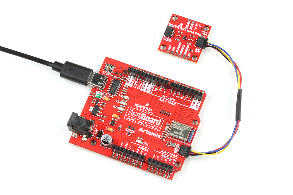
The fastest and easiest way to get started using the breakout is to connect the Qwiic connector on the breakout to a Qwiic-enabled development board like the SparkFun RedBoard Artemis with a Qwiic cable and as shown in the image below.
If you would prefer a more secure and permanent connection with the Standard Size breakout, you can solder headers or wire to the PTH header on the board.
SPI Assembly (Standard Size Only)
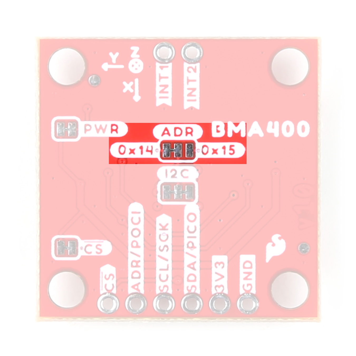
Setting the breakout up to communicate with the sensor over SPI requires completely opening the ADR jumper and we recommend soldering to the PTH header to make the connections. If you are not familiar with through-hole soldering, take a read through this tutorial:
How to Solder: Through-Hole Soldering
Along with tools for soldering, you'll need either some hookup wire or headers and jumper wires. Sever the trace between the "Center" and "Right" pads of the ADR jumper to switch to SPI mode. After opening this jumper, connect the breakout to your controller's SPI bus pins.
Remember, the BMP384 operates at 3.3V logic so make sure to connect to a board running at the same logic level like the RedBoard Artemis or use a level shifter to adjust it to the correct voltage.