SparkFun Triple Axis Accelerometer Breakout - BMA400 (Qwiic) Hookup Guide
 El Duderino
Hardware Overview
Let's take a closer look at the BMA400 and other hardware features on these Qwiic breakouts.
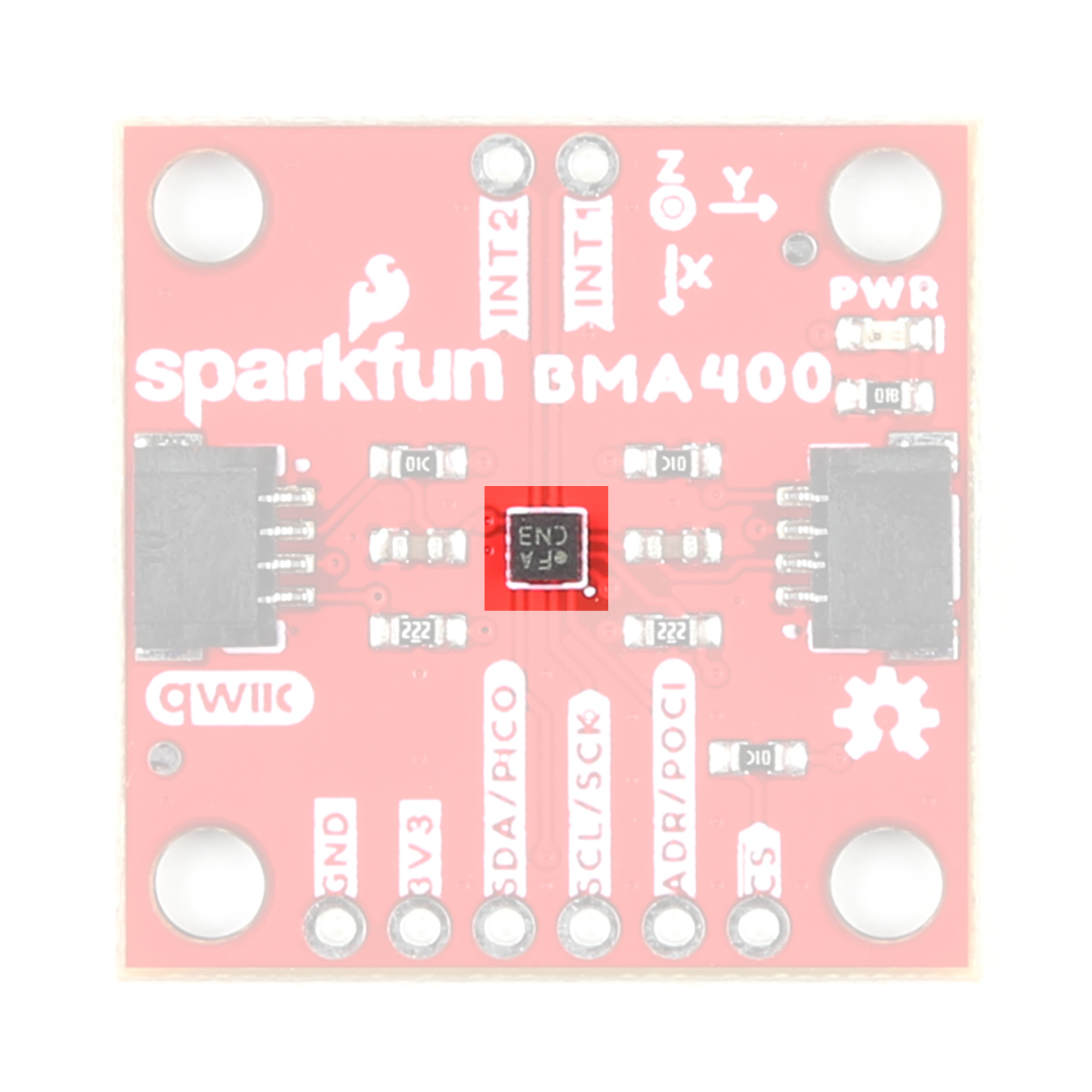
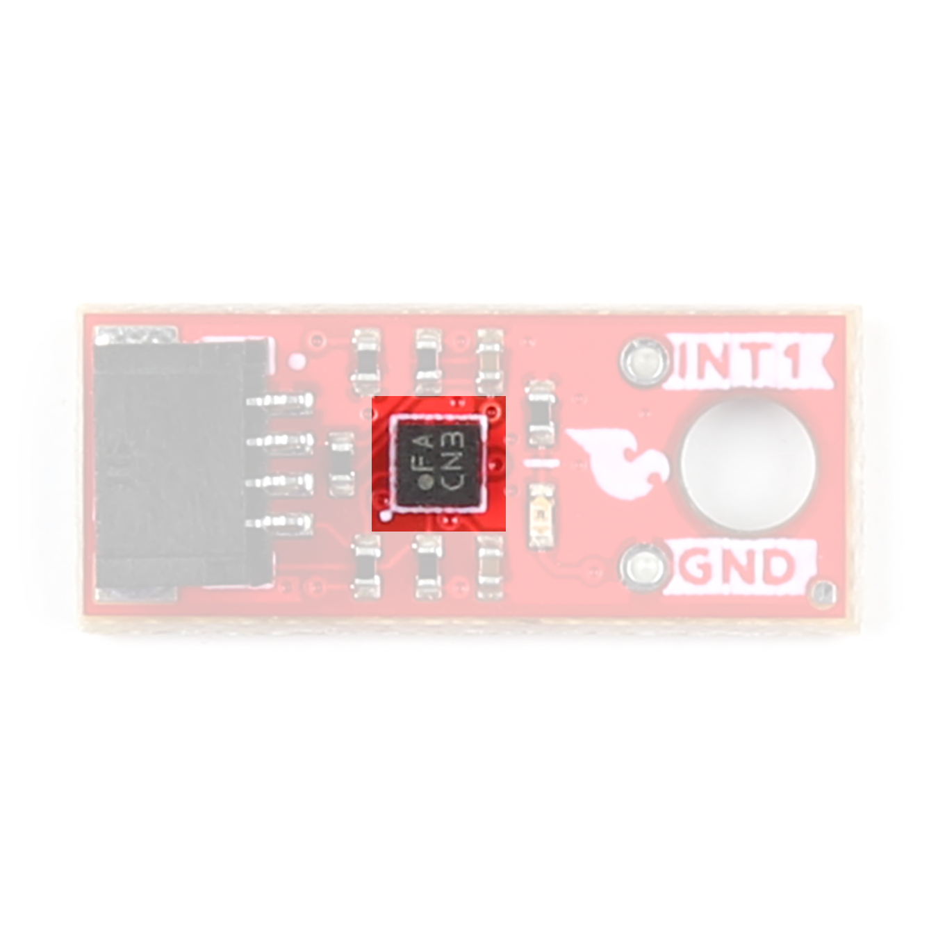
BMA400 3-Axis Accelerometer
The BMA400 3-axis accelerometer from Bosch Sensortec is an ultra-low power motion sensor with a host of interrupt features making it ideal for battery-powered activity monitoring applications.
 |
 |
The BMA400 features four user-selectable ranges of ±2/±4/±8/±16g and consumes just 14.5µA when measuring acceleration data at the highest performance settings. The BMA400 also includes a robust interrupt feature set:
- Auto Wakeup
- Auto Low Power
- Step Counter
- Activity Recognition (Running, Walking, Standing Still)
- Orientation Detection
- Tap and Double Tap
The sensor has two interrupt pins available for all of the above interrupt conditions. The table below outlines a few of the BMA400's sensing and operating parameters. For a full overview of the BMA400, refer to the datasheet.
| Parameter | Min. | Typ. | Max. | Units | Notes |
|---|---|---|---|---|---|
| Supply Voltage | 1.72 | 1.8 | 3.6 | V | Breakouts run BMA400 at 3.3V. |
| Normal Mode Current Draw | 14.5 | µA | Oversampling Rate set to 3 | ||
| Low-Power Mode Current Draw | 0.850 | Oversampling Rate set to 0 | |||
| Sleep Mode Current Draw | 0.160 | ||||
| Acceleration Range | ±2 | g | Sensitivity of 1024LSB/g | ||
| ±4 | Sensitivity of 512LSB/g | ||||
| ±8 | Sensitivity of 256LSB/g | ||||
| ±16 | Sensitivity of 128LSB/g | ||||
| Output Data Rate (ODR) | 12.5 | 800 | Hz | ODR in Low-Power mode is 25Hz |
Communication Interfaces - I2C & SPI
The standard size version of these Qwiic breakouts communicates over I2C by default but also supports communicating using SPI. The Qwiic Micro version only supports I2C communication over the Qwiic connector on the board.
 |
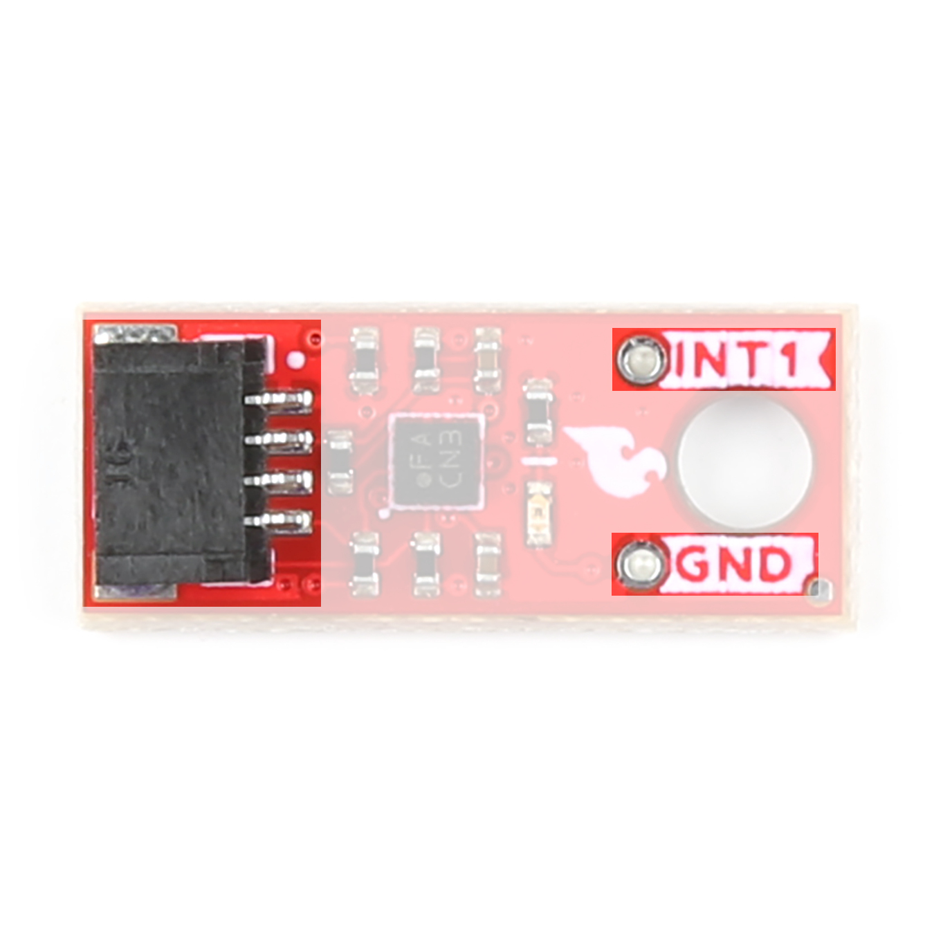 |
The standard size routes the I2C interface to a pair of Qwiic connectors as well as a 0.1"-spaced PTH header for users who prefer SPI or a traditional soldered connection. The standard-size breakout routes both INT1 and INT2 to a pair of PTH pins. The Qwiic Micro routes only INT1 to a PTH pin.
Both boards set the BMA400's I2C address to 0x14 by default. Adjust the ADR jumper to change to the alternate address (0x15) or open it completely to use the SPI interface (Standard size only). More information on this jumper in the Solder Jumpers section below.
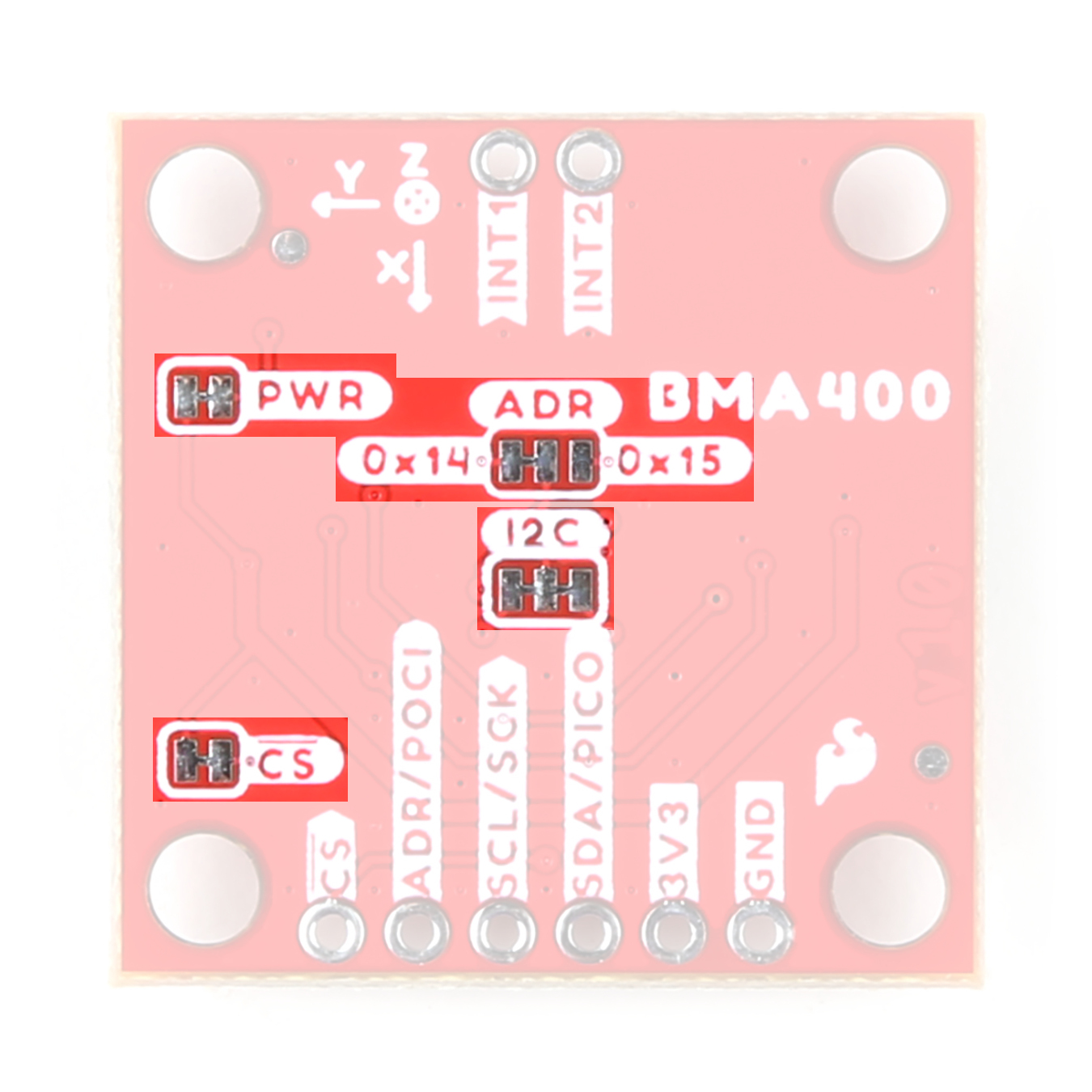
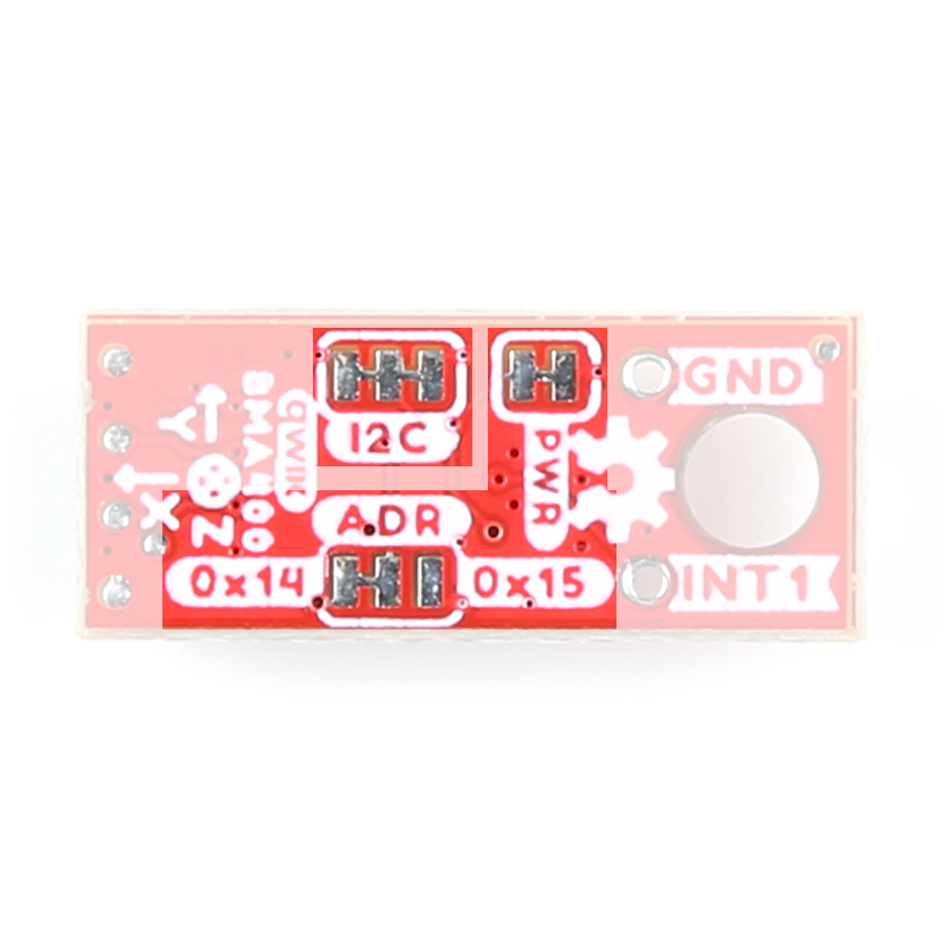
Solder Jumpers
The Standard size breakout has four solder jumpers labeled PWR, ADR, I2C, and CS. The Micro size has all but the CS jumper as the Micro version does not support SPI. Instead, the Micro version pulls the CS pin to 3.3V. The table below outlines the jumpers' labels, default state, functionality, and any notes regarding their use.
 |
 |
| Label | Default State | Function | Notes |
|---|---|---|---|
| PWR | CLOSED | Completes the Power LED circuit. | Open to disable the Power LED. |
| ADR | SEE NOTE | Sets the sensor's I2C address. | Address is 0x14 by default. Switch to 0x15 by severing the trace between the "Center" and "Left" pads and connecting the "Center" and "Right" pads. Leave open entirely to use the BMA400 over SPI (Standard size only.) |
| I2C | CLOSED | Ties the SDA/SCL lines to VCC (3.3V) through a pair of 2.2kΩ resistors. | Open the jumper to disable the pull-up resistors on the I2C lines. |
| CS* | CLOSED | Pulls the BMA400's chip select (CS) pin to VCC (3.3V) through a 10kΩ resistor. | *Standard size only. Open to disable the pull-up on CS. |
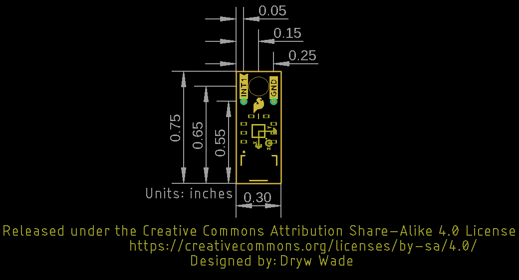
Board Dimensions
The boards match the Standard and Micro form-factors for Qwiic breakouts measuring 1" x 1" (Standard) and 0.5" x 0.3" (Micro). The Standard breakout has four mounting holes and the Micro has one. All mounting holes fit a size 4-40 screw.
 |
 |