SparkFun Thing Plus Matter - MGM240P Hookup Guide
 El Duderino
Hardware Overview
In this section we'll take a closer look at the MGM240P as well as other hardware present on the Thing Plus Matter - MGM240P.
MGM240P
The MGM240P wireless module provides a secure solution for both 802.15.4 (Matter, Zigbee, and OpenThread) and Bluetooth Low Energy 5.3 protocols, and is designed to integrate seamlessly into the Matter IoT convention. Matter aims to simplify and consolidate major Smart Home IoT ecosystems into a single, secure, and easy to use protocol.
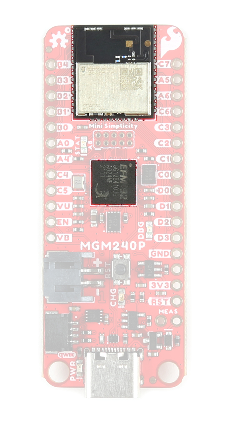
The MGM240P is built around Silicon Labs' EFR32MG24 wireless system-on-chip (SoC) that includes a 32-bit ARM Cortex M33 core processor and integrated 2.4 GHz radio, 1536 kB Flash memory, and 256 kB of RAM. The Thing Plus runs the MGM240P at 3.3V by default when powered by USB or a battery. The module has a dedicated processor core for security to allow for use with Silicon Labs' Secure Vault IoT security feature suite along with a host of software-configurable options using the Simplicity Studio IDE. This Thing Plus specifically uses the MGM240PB32VNA variant of the module which uses a built in antenna with a max transmit power of +20 dBm. For a complete overview of the MGM240P refer to the datasheet.
J-Link Debugger
The board uses the EFM32GG12B410F1024GL120-A microcontroller as a J-Link programmer and debugging IC. The Mini Simplicity Connector on the board allows users to connect an external debugger if they wish. The board pulls the debugger WAKE pin to V_USB through the LP jumper by default to have it operate in standard mode. Users can open this jumper to force the debugger into Low Power mode.
The debugger allows some seriously low-level debugging tools when used with Simplicity Studio's debugging tool. You can perform all sorts of standard debugging actions such as debugger output, placing code breaks, and can even get as granular as looking at the assembly code.
Power
The Thing Plus Matter - MGM240P offers several ways to power the board. The primary power options are the USB-C connector (also used for programming/serial communication) and 2-pin JST connector for a single-sell LiPo battery. The board includes the necessary components to charge and monitor the charge level of a connected battery.

The board also has PTH pins connected to the 3.3V, V_USB, and V_BATT nets.
USB-C
The USB-C connector on the board provides power, battery charging voltage, and a serial connection for programming and interfacing. The board also includes a USB shield jumper that controls whether or not the USB shield pin on an attached cable connects to the board's ground plane.
The 5V from V_USB connects to the 3.3V regulator as well as the VIN on the LiPo battery charger so the MCP73831 is powered with voltage present from USB so long as the CHG solder jumper is set to either current setting. Opening the jumper disables the MCP73831.
LiPo Connector and Charge Circuit
The board includes a 2-pin JST connector to plug a single-cell LiPo battery in for battery powered applications. The input voltage is regulated by a 3.3V voltage regulator. The board also features a MCP73831 Single-Cell LiPo Charge IC to recharge a connected battery when plugged in over USB-C as well as a MAX17048 Single-Cell fuel gauge to monitor battery charge level.
By default the charge current is set to 500mA. A three-way jumper labeled CHG allows users to switch between 500mA charge current to 100mA as well as disabling the charge IC when not needed. More on this and all other solder jumpers in the Solder Jumpers section below.
Pinout
The MGM240P has 26 General Purpose Input/Output (GPIO) pins that are all individually configurable through software to act as I/O pins, peripherals (SPI, I2C, etc.) or other advanced configurations such as open-drain. This allows remapping of any GPIO to any supported functionality.
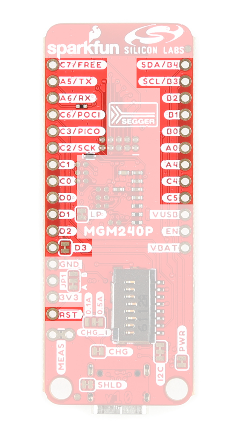
The Thing Plus Matter - MGM240P breaks out 23 of these pins to PTHs on either side of the board. The board settings configures them to deliver the following functionality:
- Serial - TX/RX
- I2C - SDA/SCL
- SPI - POCI/PICO/SCK
- Analog - A0-A5*
- GPIO - 0-6*
- Freebie - Feather-compatible Freebie pin tied to PC07
- Reset
- Enable
Peripheral Accessories
The Thing Plus MGM240P includes several peripheral accessories that allow users quick access to several features. Let's take a brief look at them.
 |
 |
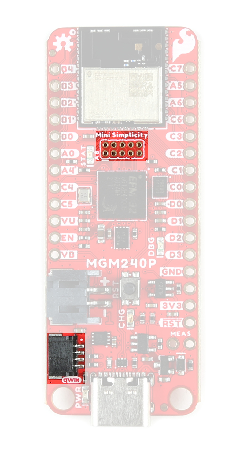
Mini Simplicity Connector
The Mini Simplicity Connector allows users a quick and direct option to connect an external debugger to the board.
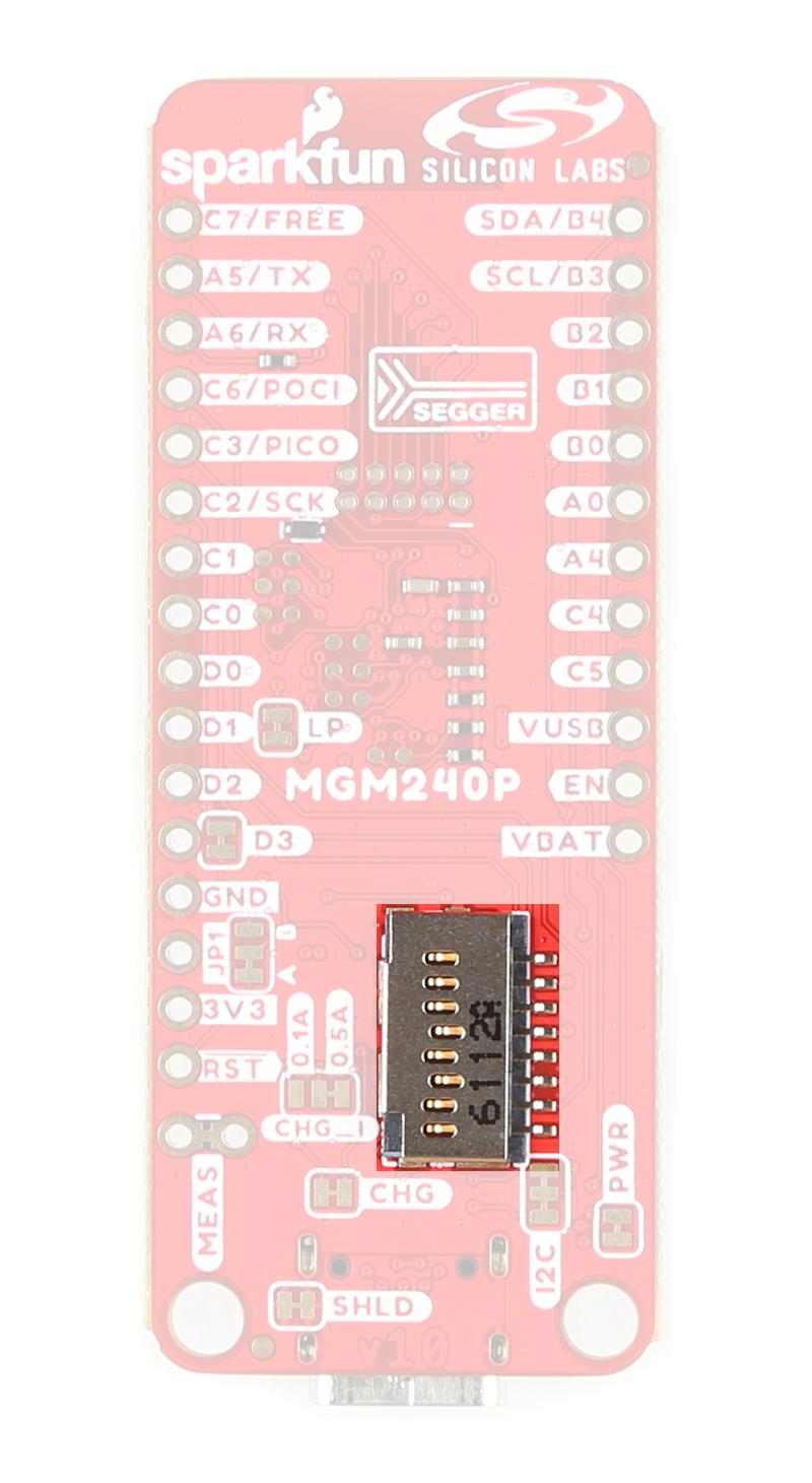
µSD Slot
The µSD card slot provides an option to connect a µSD card for extra memory space to the Thing Plus.
Qwiic Connector
The Qwiic connector provides a fast connection to the I2C bus to use with SparkFun's ever-growing Qwiic ecosystem.
LEDs
This board has four LEDs labeled PWR, STAT, CHG, and DBG.

- Power (PWR) LED - Indicates power supplied to the board.
- Status (STAT) LED - Tied to A8 for use as a general status indicator.
- Charge (CHG) LED - Indicates whether or not the charge circuit is actively charging an attached LiPo battery.
- Debugger (DBG) LED - Connects to the debugger IC's status output and can provide visual indication for debug behavior.
Solder Jumpers
If you have never worked with solder jumpers and PCB traces before or would like a quick refresher, check out our How to Work With Solder Jumpers and PCB Traces tutorial for detailed instructions and tips.
The board has nine solder jumpers for user customization. The table below outlines the jumper's label, default state, function, and any notes regarding how to use them.
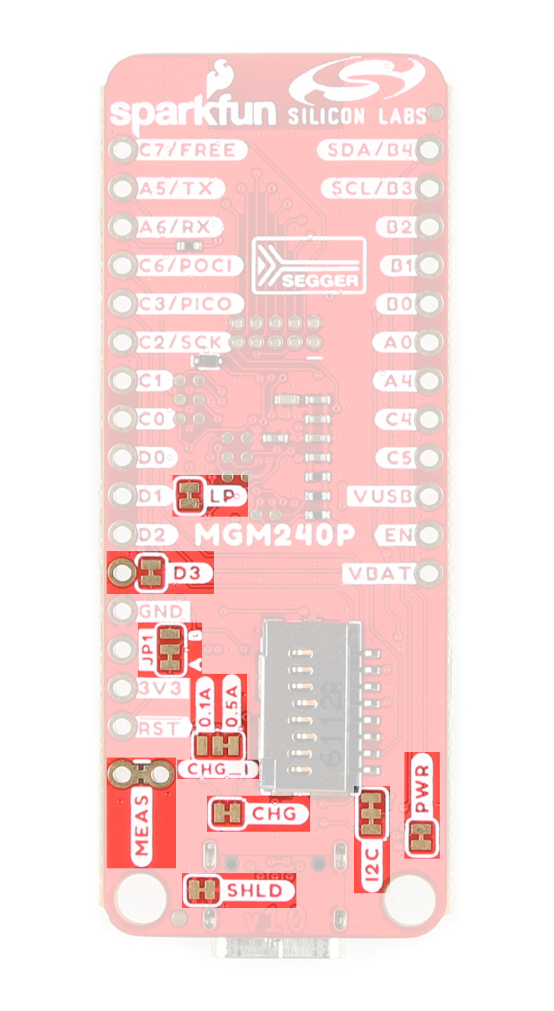
| Jumper Label | Default State | Function | Notes |
|---|---|---|---|
| PWR | CLOSED | Completes the Power LED circuit | Open to disable the Power LED. |
| CHG | CLOSED | Completes the Charge LED circuit. | Open to disable the Charge LED. |
| I2C | CLOSED | Ties SDA/SCL (PB04/PB03 respectively) to 3.3V through a pair of 2.2kΩ resistors | Open to disable pullup resistors on these pins. |
| CHG_I | SEE NOTE | Three-way jumper sets the charge current for the LiPo charge circuit. | Default setting is 500mA (0.5A label). Alternate is 100mA (0.1A label). Open completely to disable LiPo charger. |
| JP1 | SEE NOTE | Three-way jumper that routes the MGM240P's RESET pin either to the Reset Button (Default) or the A0 PTH. | Connect the JP1 jumper to the A0 side to reroute the RESET pin to allow toggling of A0 by an external connection to reset the MGM240P. |
| D3 | CLOSED | Ties A0 PTH to PD03. | Open to isolate PD03 if JP1 is set to the A0 side. |
| SHLD | CLOSED | Connects the USB-C shield pin to the PCB's ground plane. | Open to isolate the USB-C shield pin from the ground. |
| MEAS | CLOSED | Completes the power input circuit. | Open and use a digital multimeter to complete the circuit and measure current drawn by the board. |
| LP | CLOSED | Ties the J-Link debugger IC Wake pin to V_USB. | Open to force the debugger into Low Power mode. Open for battery powered applications where V_USB is present through a charging bank on USB-C connector. |
Board Dimensions
The Thing Plus - MGM240P matches the Thing Plus footprint to work with all Thing Plus-compatible accessories and shields and measures 2.30" x 0.90" (58.42mm x 22.86mm). The two mounting holes on this Thing Plus fit a 4-40 screw
