SparkFun Thing Plus Matter - MGM240P Hookup Guide
Introduction
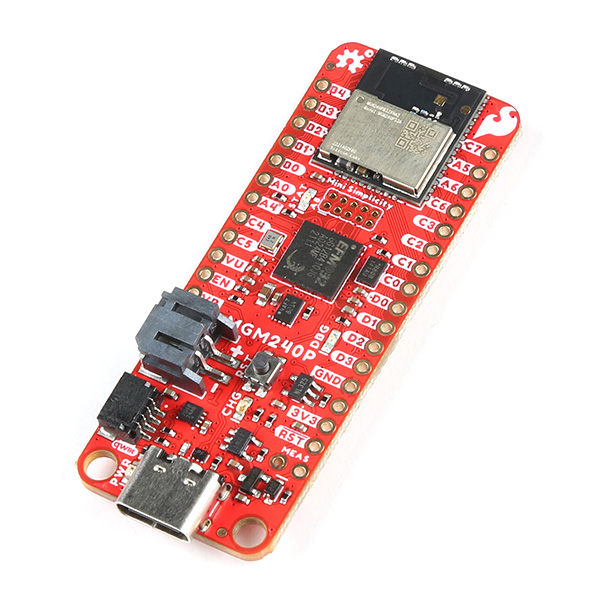
The SparkFun Thing Plus Matter - MGM240P is the first easily accessible board of its kind that combines Matter® and SparkFun's Qwiic ecosystem for agile development and prototyping of Matter-based IoT devices. The board features the MGM240P wireless module from Silicon Labs®. The MGM240P provides secure connectivity for both 802.15.4 (Matter, Zigbee®, and OpenThread®) and Bluetooth Low Energy 5.3 protocols and is built to integrate seamlessly into the Matter IoT protocol using the Simplicity Studio IDE from Silicon Labs.
You may be curious as to what exactly Matter is. In a nutshell, Matter allows for consistent operation between smart home devices and IoT platforms without an Internet connection, even from different providers. This allows communication between major IoT ecosystems to create a single wireless protocol that is easy, reliable and secure to use.
This guide covers the hardware present on this Thing Plus development board, basic assembly, and a quick intro to using the Thing Plus Matter in Silicon Labs' Simplicity Studio development environment.
Required Materials
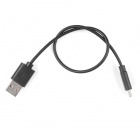
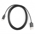
All you need to follow along with this tutorial is the SparkFun Thing Plus MGM240P as well as a USB-C cable to connect it to your computer for programming. You may also want a single-cell LiPo battery to power the board in your application.
Optional Accessories
Depending on your application's needs, you may want some additional accessories along with the Thing Plus Matter - MGM240P and USB-C cable.
LiPo Battery
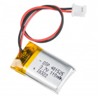
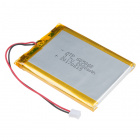
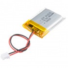
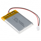
The Thing Plus Matter includes a 2-pin JST connector to connect a single-cell lithium-ion battery for power in mobile applications. Below are a few options we recommend:
Lithium Ion Battery - 1Ah
PRT-13813Headers
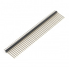
Headers allow you connect external parts to your board with just a set of jumper wires for prototyping circuits with a breadboard. The list below outlines a few options we recommend. If you don't find what you need, check out our Headers Category. If you need soldering tools, head over to our Soldering Category:
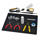
SparkFun Beginner Tool Kit
TOL-14681Solder Jumper Modification
The Thing Plus Matter - MGM240P has several solder jumpers users can modify to change behavior on the board. Modifying the jumpers requires a knife and soldering equipment. The list below covers some recommended options but in case you do not find what you need there, head over to our Soldering Category:
Weller WLC100 Soldering Station
TOL-14228Suggested Reading
Before getting started with this Hookup Guide, you may want to read through the tutorials below if you are not familiar with the concepts covered in them or want a refresher:
How to Solder: Through-Hole Soldering
Serial Communication
Serial Peripheral Interface (SPI)
Logic Levels
I2C
Analog vs. Digital
Bluetooth Basics
How to Work with Jumper Pads and PCB Traces
Hardware Overview
In this section we'll take a closer look at the MGM240P as well as other hardware present on the Thing Plus Matter - MGM240P.
MGM240P
The MGM240P wireless module provides a secure solution for both 802.15.4 (Matter, Zigbee, and OpenThread) and Bluetooth Low Energy 5.3 protocols, and is designed to integrate seamlessly into the Matter IoT convention. Matter aims to simplify and consolidate major Smart Home IoT ecosystems into a single, secure, and easy to use protocol.
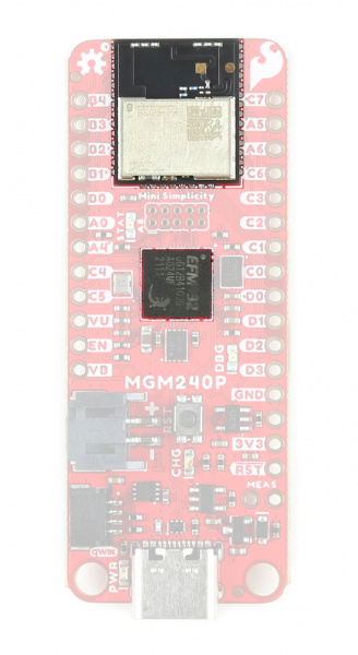
The MGM240P is built around Silicon Labs' EFR32MG24 wireless system-on-chip (SoC) that includes a 32-bit ARM Cortex M33 core processor and integrated 2.4 GHz radio, 1536 kB Flash memory, and 256 kB of RAM. The Thing Plus runs the MGM240P at 3.3V by default when powered by USB or a battery. The module has a dedicated processor core for security to allow for use with Silicon Labs' Secure Vault IoT security feature suite along with a host of software-configurable options using the Simplicity Studio IDE. This Thing Plus specifically uses the MGM240PB32VNA variant of the module which uses a built in antenna with a max transmit power of +20 dBm. For a complete overview of the MGM240P refer to the datasheet.
J-Link Debugger
The board uses the EFM32GG12B410F1024GL120-A microcontroller as a J-Link programmer and debugging IC. The Mini Simplicity Connector on the board allows users to connect an external debugger if they wish. The board pulls the debugger WAKE pin to V_USB through the LP jumper by default to have it operate in standard mode. Users can open this jumper to force the debugger into Low Power mode.
The debugger allows some seriously low-level debugging tools when used with Simplicity Studio's debugging tool. You can perform all sorts of standard debugging actions such as debugger output, placing code breaks, and can even get as granular as looking at the assembly code.
Power
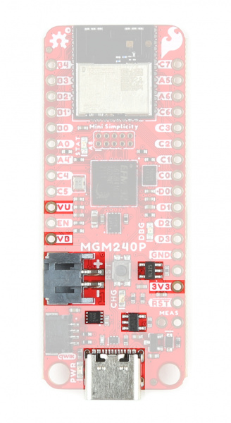
The Thing Plus Matter - MGM240P offers several ways to power the board. The primary power options are the USB-C connector (also used for programming/serial communication) and 2-pin JST connector for a single-sell LiPo battery. The board includes the necessary components to charge and monitor the charge level of a connected battery.
The board also has PTH pins connected to the 3.3V, V_USB, and V_BATT nets.
USB-C
The USB-C connector on the board provides power, battery charging voltage, and a serial connection for programming and interfacing. The board also includes a USB shield jumper that controls whether or not the USB shield pin on an attached cable connects to the board's ground plane.
The 5V from V_USB connects to the 3.3V regulator as well as the VIN on the LiPo battery charger so the MCP73831 is powered with voltage present from USB so long as the CHG solder jumper is set to either current setting. Opening the jumper disables the MCP73831.
LiPo Connector and Charge Circuit
The board includes a 2-pin JST connector to plug a single-cell LiPo battery in for battery powered applications. The input voltage is regulated by a 3.3V voltage regulator. The board also features a MCP73831 Single-Cell LiPo Charge IC to recharge a connected battery when plugged in over USB-C as well as a MAX17048 Single-Cell fuel gauge to monitor battery charge level.
By default the charge current is set to 500mA. A three-way jumper labeled CHG allows users to switch between 500mA charge current to 100mA as well as disabling the charge IC when not needed. More on this and all other solder jumpers in the Solder Jumpers section below.
Pinout
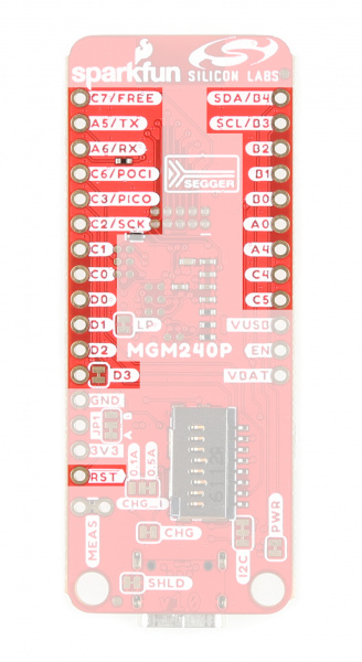
The MGM240P has 26 General Purpose Input/Output (GPIO) pins that are all individually configurable through software to act as I/O pins, peripherals (SPI, I2C, etc.) or other advanced configurations such as open-drain. This allows remapping of any GPIO to any supported functionality.
The Thing Plus Matter - MGM240P breaks out 23 of these pins to PTHs on either side of the board. The board settings configures them to deliver the following functionality:
- Serial - TX/RX
- I2C - SDA/SCL
- SPI - POCI/PICO/SCK
- Analog - A0-A5*
- GPIO - 0-6*
- Freebie - Feather-compatible Freebie pin tied to PC07
- Reset
- Enable
Peripheral Accessories
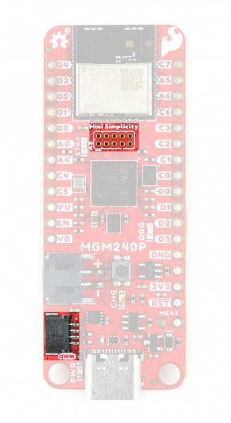
The Thing Plus MGM240P includes several peripheral accessories that allow users quick access to several features. Let's take a brief look at them.
 |
 |
Mini Simplicity Connector
The Mini Simplicity Connector allows users a quick and direct option to connect an external debugger to the board.
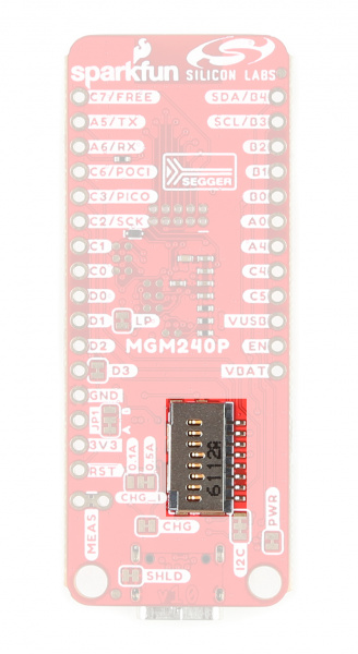
µSD Slot
The µSD card slot provides an option to connect a µSD card for extra memory space to the Thing Plus.
Qwiic Connector
The Qwiic connector provides a fast connection to the I2C bus to use with SparkFun's ever-growing Qwiic ecosystem.
LEDs
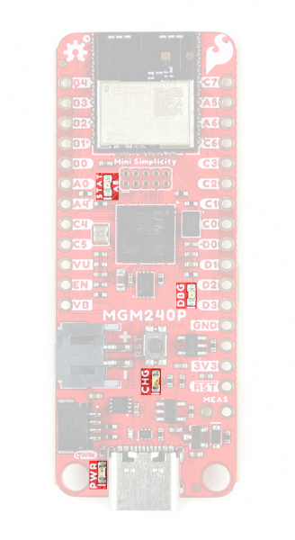
This board has four LEDs labeled PWR, STAT, CHG, and DBG.
- Power (PWR) LED - Indicates power supplied to the board.
- Status (STAT) LED - Tied to A8 for use as a general status indicator.
- Charge (CHG) LED - Indicates whether or not the charge circuit is actively charging an attached LiPo battery.
- Debugger (DBG) LED - Connects to the debugger IC's status output and can provide visual indication for debug behavior.
Solder Jumpers
If you have never worked with solder jumpers and PCB traces before or would like a quick refresher, check out our How to Work With Solder Jumpers and PCB Traces tutorial for detailed instructions and tips.
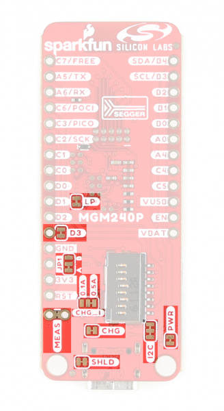
The board has nine solder jumpers for user customization. The table below outlines the jumper's label, default state, function, and any notes regarding how to use them.
| Jumper Label | Default State | Function | Notes |
|---|---|---|---|
| PWR | CLOSED | Completes the Power LED circuit | Open to disable the Power LED. |
| CHG | CLOSED | Completes the Charge LED circuit. | Open to disable the Charge LED. |
| I2C | CLOSED | Ties SDA/SCL (PB04/PB03 respectively) to 3.3V through a pair of 2.2kΩ resistors | Open to disable pullup resistors on these pins. |
| CHG_I | SEE NOTE | Three-way jumper sets the charge current for the LiPo charge circuit. | Default setting is 500mA (0.5A label). Alternate is 100mA (0.1A label). Open completely to disable LiPo charger. |
| JP1 | SEE NOTE | Three-way jumper that routes the MGM240P's RESET pin either to the Reset Button (Default) or the A0 PTH. | Connect the JP1 jumper to the A0 side to reroute the RESET pin to allow toggling of A0 by an external connection to reset the MGM240P. |
| D3 | CLOSED | Ties A0 PTH to PD03. | Open to isolate PD03 if JP1 is set to the A0 side. |
| SHLD | CLOSED | Connects the USB-C shield pin to the PCB's ground plane. | Open to isolate the USB-C shield pin from the ground. |
| MEAS | CLOSED | Completes the power input circuit. | Open and use a digital multimeter to complete the circuit and measure current drawn by the board. |
| LP | CLOSED | Ties the J-Link debugger IC Wake pin to V_USB. | Open to force the debugger into Low Power mode. Open for battery powered applications where V_USB is present through a charging bank on USB-C connector. |
Board Dimensions
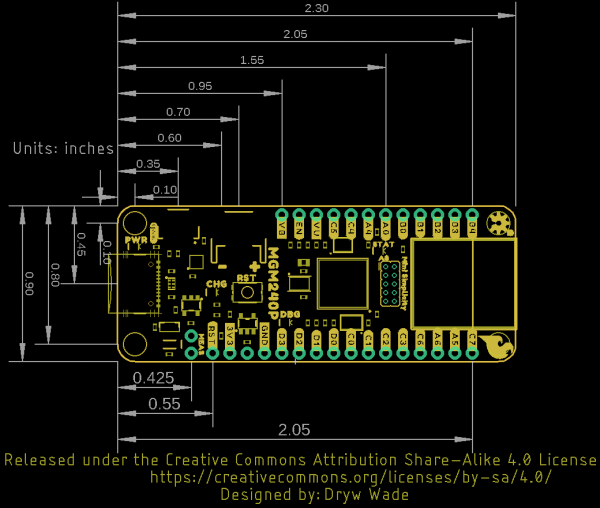
The Thing Plus - MGM240P matches the Thing Plus footprint to work with all Thing Plus-compatible accessories and shields and measures 2.30" x 0.90" (58.42mm x 22.86mm). The two mounting holes on this Thing Plus fit a 4-40 screw
Hardware Assembly
Now that we're familiar with the hardware on this Thing Plus it's time to assemble the board into a prototyping circuit or simply plug it into our computer with a USB-C cable and get right to programming.
Basic Assembly
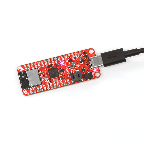
For those who want to jump right in to using the Thing Plus Matter - MGM240P on its own or just with the wireless capabilities, all you need to do is plug the board into your computer using a USB-C cable.
Soldering Headers
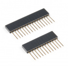
Users who want to assemble a prototyping circuit with the Thing Plus should solder headers of their choice to the board to plug it into a breadboard. We recommend something like this Feather Stackable Header Kit.
Software Setup
The MGM240P uses Silicon Labs' Simplicity Studio IDE as a development tool for programming, debugging, customizing, etc. In this section we'll cover the basics of installing the IDE and adding the Thing Plus Matter.
Install and Open Simplicity Studio
Simplicity Studio is available for Windows, Mac OSX and Ubuntu operating systems. You can find the installer download for your operating system by clicking the button below:
Silicon Labs requires you to create a (free) account to download Simplicity Studio so make one if you do not have one already. Once the installer finishes downloading, open it and follow the installation instructions.
Simplicity Studio Launcher
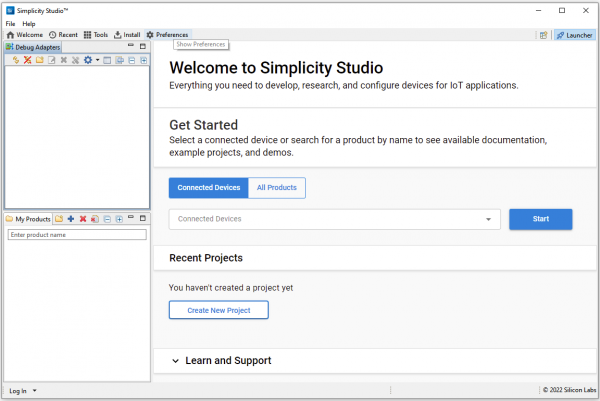
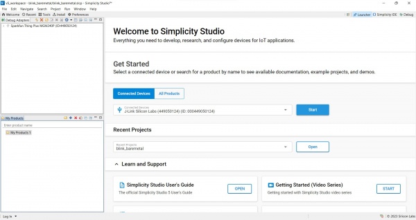
When you first open Simplicity Studio you'll be greeted by the Launcher window. The default Launcher window lets users install board files for both connected devices and by searching for a supported product. It also lists any recent projects you've worked on as well as links to user guides and support documentation.
On the left side there are two windows for any debug adapters (top) and all installed products (bottom). In the very top right of the screen you'll see the tabs to switch between the launcher, the Simplicity IDE and the Debug window. We'll be using the IDE tab in the next section once we finish installing the Thing Plus Matter into Simplicity Studio.
Adding the Thing Plus Matter - MGM240P
Simplicity Studio makes adding devices extremely easy by just connecting the device to your computer over USB and then selecting "Connected Devices". It automatically checks the device ID to matching supported products and should display either as a J-Link Silicon Labs debugger (prior to install) or "SparkFun Thing Plus MGM240P" as the connected device.
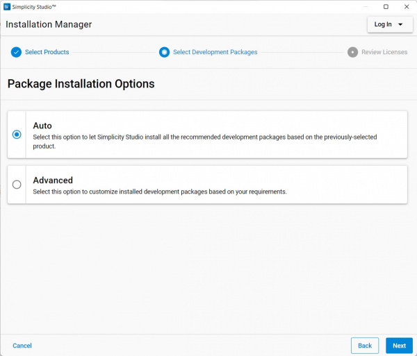
With the connected Thing Plus selected, click "Start". This opens the Installation Manager window where you can select either "Auto" or "Advanced" installation. Most users should select "Auto" and then click "Next". You'll be prompted to agree to licensing agreements. Once you have agreed, click "Finish" and it will install all necessary software, drivers and other packages to use the Thing Plus Matter in Simplicity Studio.
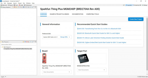
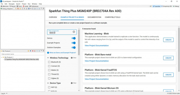
The install process can take a few minutes and once it completes you'll need to restart the program. After restarting, your Launcher window should update and look similar to the screenshot below:
This window contains several tabs that cover the general overview of the board, examples, documentation and compatible tools. Feel free to explore as much as you'd like but for now we'll move on to a basic "Blink" example to make sure everything was set up correctly and the Thing Plus Matter is working.
Silicon Labs Documentation
For comprehensive information on using Simplicity Studio, Silicon Labs has an in-depth user guide for the IDE available here:
If you're itching to integrate your Thing Plus with a Matter-compatible device, Silicon Labs has documentation for Matter development here:
They also have much more documentation covering other applications including Thread, other wireless protocols, and the Gecko SDK used in Simplicity Studio available on their main documentation page here:
Blink Example
Now that the Thing Plus Matter - MGM240P is installed in Simplicity Studio we can move on to a basic test to make sure everything is working as intended. For this example we'll be setting up and uploading a Blink test to turn the Status LED on and off.
Blink Example
In the Launcher with the SparkFun Thing Plus MGM240P selected for your product, navigate to the "Example Projects & Demos" tab. Now type "Blink" into the "Filter on keywords" search bar and select "Platform - Blink Bare-metal" and click "Create".
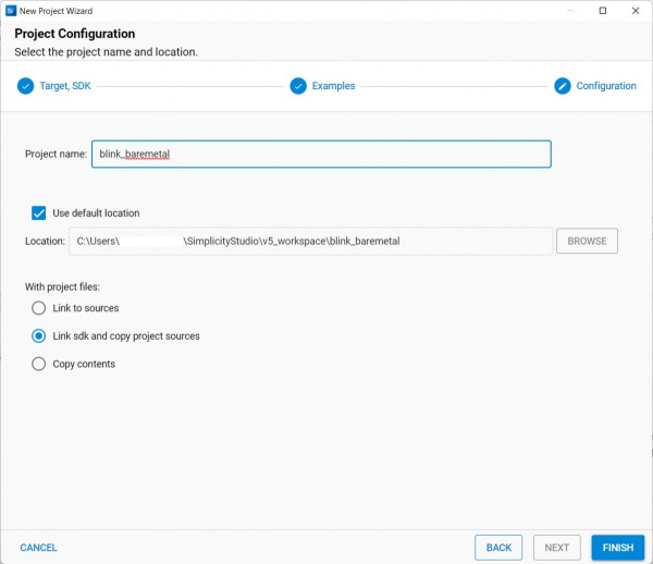
This opens the New Project Wizard window where you can change the project name, filepath, and project file options. For now, leave all of that with the default settings and click "Finish".
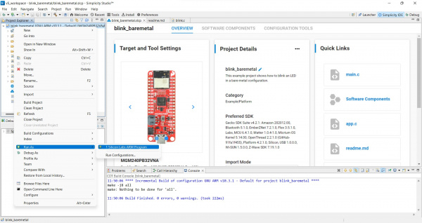
Once you've created the new project you can double-click on the containing folder in the "Project Explorer" window to open all the files included with the Blink project which includes any binaries, configs, header and C files if you prefer. For now, we're just going to build and flash the project to get the Status LED blinking. To do that, right click on the "blink_baremetal" folder and scroll down to "Run As" and select "1 Silicon Labs ARM Program". This builds and flashes the project to your board and once it completes the Blue STAT LED should be blinking on and off every second.
This is obviously one of the most basic projects for the Thing Plus Matter so from here you can explore other example projects and demos for the Thing Plus or start building your own.
Troubleshooting
Power Consumption Tips
Power consumption by this board varies depending on how it is configured and powered. Below are our current consumption test results for various power options with the MGM240P operating in Low Power mode:
- Regulated 3.3V input on 3V3 pin - 15µA
- LiPo JST Connector/VBAT pin - 120µA
- USB-C/VUSB pin (LP and CHG jumpers cut) - 250µA
- USB-C/VUSB pin (only LP jumper cut) - 300µA
- USB-C/VUSB pin (neither jumper cut) - 21mA
As you can see, for lowest current consumption, powering the board with a regulated 3.3V input directly to the 3.3V pin draws significantly less current as it bypasses the voltage regulator and battery charge/monitoring components. All of these tests were performed with the PWR jumper OPEN to disable the Power LED.
Driver Installation
Most operating systems will not recognize the Thing Plus Matter as a USB device by default. To install drivers, download and install the Simplicity Studio IDE and then install the Thing Plus Matter package to the IDE. This process will install all necessary board packages for the Thing Plus including USB drivers. Refer to our Getting Started with Simplicity Studio guide or Silicon Labs' Simplicity Studio documentation for detailed instructions.
General Troubleshooting
If you need technical assistance and more information on a product that is not working as you expected, we recommend heading on over to the SparkFun Technical Assistance page for some initial troubleshooting.
If you don't find what you need there, the SparkFun Forums are a great place to find and ask for help. If this is your first visit, you'll need to create a Forum Account to search product forums and post questions.
Resources and Going Further
That's all for this guide. For more information about the SparkFun Thing Plus Matter - MGM240P, check out the following resources:
SparkFun Thing Plus Matter - MGM240P Resources
Silicon Labs Resources
- Datasheet (MGM240P)
- Simplicity Studio IDE
- Simplicity Studio User Guide
- GeckoSDK User Guide
- Silicon Labs Matter
Looking to use the Thing Plus Matter - MGM240P with the Matter platform? Check out this tutorial on how to set up the Thing Plus with a Google Nest Hub™:
