SparkFun Satellite Transceiver Kit - Swarm M138 Hookup Guide
 PaulZC
 Introduction
Looking for a low-cost way to send and receive data messages via satellite? This is it! With a clear view of the sky, the Satellite Transceiver Breakout - Swarm M138 allows you to send and receive short messages. It works anywhere in the world, including the polar regions, far beyond the reach of WiFi and Cellular networks. It is perfect for a variety of low-bandwidth use cases: from connecting people and tracking vehicles, ships, or packages to relaying sensor data for agriculture, energy, and industrial IoT applications. The built-in GNSS receiver makes it perfect for many tracking applications.
We created the Satellite Transceiver Breakout to make using the Swarm M138 modem as easy as possible. Want to connect it to your laptop or Raspberry Pi and send and receive messages anywhere? You can absolutely do that. Want to hook it up to your Arduino board and send and receive messages via the modem's 3.3V UART Serial interface? You can absolutely do that too!
Let's get started!

Suggested Reading
Want to read around the subject? You may find it useful to read these tutorials first:
Serial Communication
Logic Levels
Serial Terminal Basics
How to Work with Jumper Pads and PCB Traces
Three Quick Tips About Using U.FL
How to Install CH340 Drivers
What's In The Box?
The SparkFun Satellite Transceiver Kit - Swarm M138 contains everything you need to get started with the Swarm network:
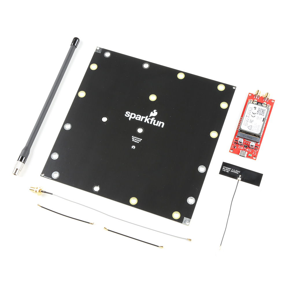
- Swarm M138 Modem
- SparkFun Satellite Transceiver Breakout
- Swarm VHF Antenna and SparkFun Ground Plane
- Molex adhesive u.FL GNSS Antenna
- 2 x 25mm u.FL cables, u.FL to SMA adapter and 2 x M2.5 screws
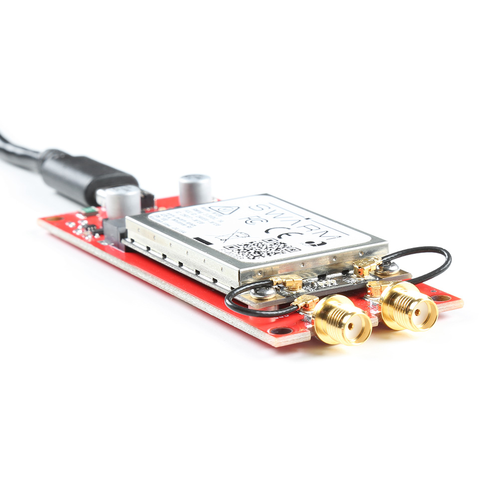
The M138 modem is a Mini-PCI Express (mPCIe) format board. Installing it is as easy as slotting it into the matching connector on the Breakout board and securing it in place with the two M2.5 screws. We'll talk about Hardware Assembly in more detail below.
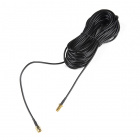
The modem has two u.FL antenna connections on it, one marked "VHF" (for the Very High Frequency signal used to communicate with the Swarm satellites) and a separate one for satellite navigation (marked "GPS"). You can, if you wish, connect the provided antennas directly to the u.FL connectors on the modem. Or, you can use the provided 25mm u.FL cables to connect the modem to the robust SMA connections on the Breakout.
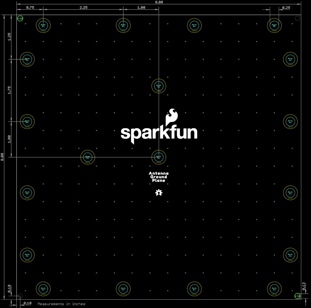
The Swarm antenna is a purpose-designed coiled quarter-wave antenna tuned to the Swarm satellite frequencies. It does require a ground plane and so we've included one of those in the box too! It comes with mounting holes to allow it to be secured to (e.g.): 2" or 1.5" antenna pole, a camera tripod, or a handrail.
SMA Male to SMA Female - 10m (RG174)
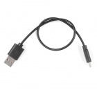
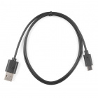
CAB-17495If you're going to connect the Breakout to your computer, laptop or Raspberry Pi, you're going to need a USB-C cable too:


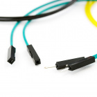
Going to connect the Breakout to your Arduino board? You will probably need: break away headers and jumper wires. 2-pin jumpers will be useful for re-linking the CH340 connections later.


Swarm Satellite
Swarm's mission is to connect people and devices anywhere, at all times, at the lowest cost.
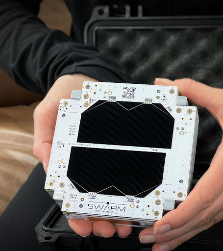
If you've used satellite communication systems in the past, you'll know that the message costs can be high if you're sending a lot of data. Swarm are changing that. Their uniquely small satellites are the smallest operational satellites in space, at just ¼U (11 x 11 x 2.8 cm). Because of their small size, they cost much less to launch than most satellites, and these savings are passed along to their customers.
The current list of approved countries / regions for the M138 Modem is: USA, Antarctica, Australia, Austria, Brazil, Canada, Colombia, Denmark, Georgia, Germany, Greenland, Iceland, Ireland, New Zealand, Netherlands, Spain, Sweden, United Kingdom and International Waters (12 nautical miles offshore).
Swarm continues to grow this list of approved countries as quickly as possible. Customers will receive regular updates on approved regions through the Swarm newsletter.
Overview of the Swarm Network
When a SpaceBEE passes over any given location, it will send out beacon packets to Swarm Modems that are in their receiver state. The Modem’s antenna will need to have a clear view of the sky, and a low RF noise environment to receive this satellite beacon.
Format of a satellite beacon packet:
$RT RSSI=,SNR=,FDEV =,TS=,DI=*xx
Once the Modem receives this satellite beacon, it will attempt to transmit any queued transmission packets to the satellite. Message packets that are successfully received by the satellite will then be acknowledged by the satellite back to the Modem. The Modem will then discard the message packet from its outgoing transmission queue.
The Swarm M138 Modem can store a maximum of 1000 outgoing message packets. Each message packet is held for a default duration of 48 hours, which is user configurable, after which the packet will be discarded if not transmitted.
The satellite will then carry that message packet until it passes over a Swarm ground station. The satellite will downlink the message packet to the ground station after which the data will be routed to Swarm’s cloud platform named the Swarm Hive. The user can then view their data on Hive, or extract that data using Swarm’s REST API, or webhooks.
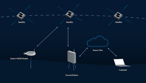
The Swarm Hive will retain data for 30 days before it is discarded, so it is best to pull that data from the Hive to reference it later. Swarm has a Python Script example that you can download by clicking here.
Hardware Overview
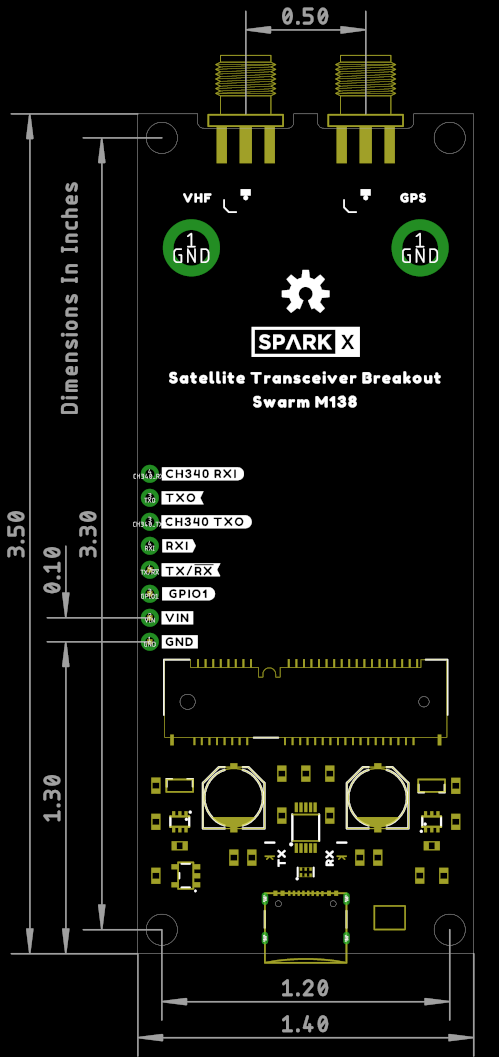
Swarm M138 Modem
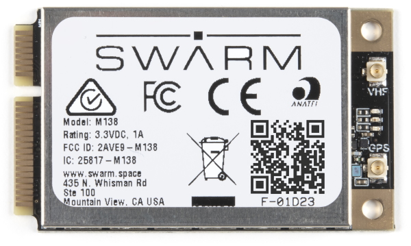
At the heart of our product is a Swarm M138 satellite modem. This is a Mini-PCI Express Card containing both the satellite modem and a very capable u-blox GNSS receiver, all in one integrated package! It can operate from a wide range of supply voltages: 3.0V Min; 5.0V Max. Its standard 3.3V CMOS serial UART interface and NMEA-style command set makes it easy to integrate into your project.
USB-C and CH340
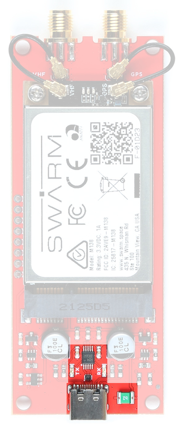
Our board includes a USB-C interface for power and/or serial data, in addition to a full set of breakout pins. Want to plug it into your laptop or Raspberry Pi and use it to communicate out in the field? You can absolutely do that!
We've included our standard CH340E interface chip to convert USB to serial. On Windows, you may need to install a driver and we have a tutorial to help with that:
How to Install CH340 Drivers
We've included a 2A resettable fuse too, just in case anything goes wrong.
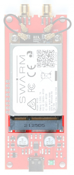
mPCIe Connector
 |
 |
|---|---|
| mPCIe connector | Screw Fixings |
The M138 modem is a very nicely designed piece of kit. The mPCIe card-edge connection makes it really easy to integrate. Two M2.5 screws secure the modem in position.
SMA Connections
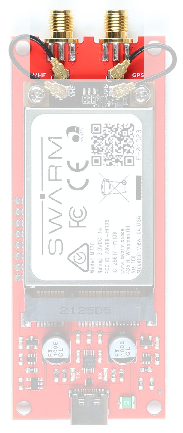
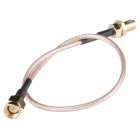
You can connect your antennas straight to the u.FL connectors on the modem itself. However, for a more robust connection, you may want to use the included 25mm u.FL cables to connect the modem to the two threaded SMA connections on the Breakout.
The "VHF" (Very High Frequency) connection is for the Swarm satellite antenna. Don't forget that the Swarm antenna requires a ground plane. There is one included in the box.
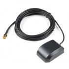
The "GPS" connection is for the mandatory GNSS satellite antenna. The modem will not work correctly unless it is aware of its location and the time, which it gets from GNSS. You can use the included Molex adhesive antenna, or you may prefer to use your own active or passive GNSS antenna. The Molex antenna is designed to be stuck to a window or another electrically-transparent surface. If you stick it to a ground plane or another conductive surface, you will not receive a signal. Peeling it off again is difficult, so please think before you stick!
Power Circuitry

The Breakout includes a dual "ideal diode" power mux circuit, allowing the modem to draw power from the USB connector or the VIN breakout pin with ~zero voltage drop. Two large 100 μF capacitors provide the necessary supply rail decoupling.
Please refer to the schematic for more details.
LEDs
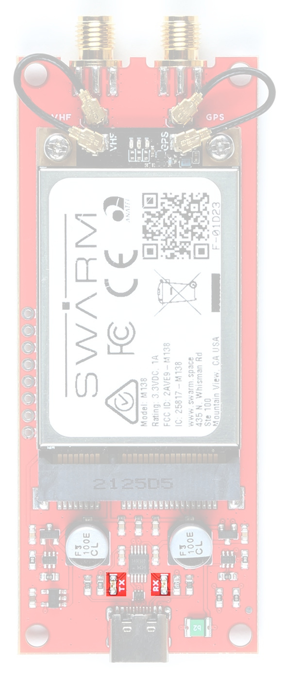
The Breakout has TX and RX LEDs connected to the CH340 signals. These can be disabled if required by cutting the TX and RX jumpers on the bottom of the board.
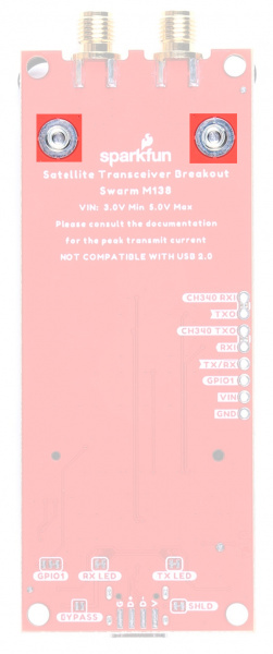
Breakout Pins
The table below describes the function of each of the Satellite Transceiver Breakout - Swarm M138 breakout pins:

| Pin Name | Function | Description | Notes |
|---|---|---|---|
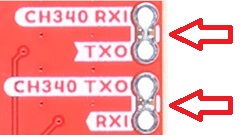
| CH340 RXI | Input | CH340 USB Interface: Receive Data In. | Logic level is 3.3V. |
| TXO | Output | Swarm Serial (UART) Interface: Transmit Data Out. | Logic level is 3.3V. By default this pin is linked to CH340 RXI. Open the jumper to isolate. |
| CH340 TXO | Output | CH340 USB Interface: Transmit Data Out. | Logic level is 3.3V. |
| RXI | Input | Swarm Serial (UART) Interface: Receive Data In. | Logic level is 3.3V. By default this pin is linked to CH340 TXO. Open the jumper to isolate. |
| TX/RX | Output | Swarm TX / RX pin. | Logic level is 3.3V. High during TX, low during RX. |
| GPIO1 | I/O (Configurable) | Swarm GPIO1 pin. | Logic level is 3.3V. Can be configured in many different ways. See below for more details. |
| VIN | Power | Power input. | 3.0V Min. 5.0V Max. |
| GND | Power | Power ground / 0V. |
Power can be provided via the USB connector or the VIN pin, or both. The modem will draw power from whichever voltage is higher. The on-board "ideal diode" power mux circuit allows both to be connected simultaneously.
By default:
- Modem TXO is connected to CH340 RXI
- Modem RXI is connected to CH340 TXO
You will need to open the jumper links on the back of the board to use the TXO and RXI pins directly.
You may find it useful to read this tutorial first:
How to Work with Jumper Pads and PCB Traces
GPIO1
GPIO1 is a multi-function input/output pin. It can be configured into different modes via the GP command:
| Mode | Description |
|---|---|
| 0 | Analog, pin is internally disconnected and not used (default) |
| 1 | Analog ADC, pin can be read to measure input voltage (0-3.3V) |
| 2 | Input, pin can be read as a general purpose digital input (High or Low) |
| 3 | Input, low-to-high transition exits sleep mode |
| 4 | Input, high-to-low transition exits sleep mode |
| 5 | Output (Open Drain), set low as a general purpose digital output |
| 6 | Output (Open Drain), set high as a general purpose digital output |
| 7 | Output (Open Drain), low indicates unread messages pending for user |
| 8 | Output (Open Drain), high indicates unread messages pending for user |
| 9 | Output (Open Drain), low indicates unsent messages pending for transmit |
| 10 | Output (Open Drain), high indicates unsent messages pending for transmit |
| 11 | Output (Open Drain), low indicates unread or unsent messages |
| 12 | Output (Open Drain), high indicates unread or unsent messages |
| 13 | Output (Open Drain), low indicates sleep mode is active. Otherwise output is high |
| 14 | Output (Open Drain), high indicates sleep mode is active. Otherwise output is low |
We've included both pull-up and pull-down resistors for GPIO1, configurable via a dual split pad jumper. By default, GPIO1 is pulled up to 3.3V so that the open drain output modes generate the correct logic level output. You can remove the pull-up by changing the jumper:
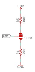
GPIO1 can sink a maximum of 8mA.
TX/RX
TX/RX is a push-pull output which is: high (3.3V) when the modem is transmitting; low (0V) when the modem is receiving or idle.
Hardware Assembly
Assembling the M138 modem onto the Breakout is very easy:
- Remove the two M2.5 screws from the standoffs
- We recommend the classic SparkFun reversible mini-screw driver, MicroMod Screwdriver, or the fancier pocket screw driver set but any #00, #0, or #1 Phillip's head driver will work.
- Align the slot of the modem's mPCIe connection with the key of the Breakout connector
- Insert the modem at an angle into the connector
- The modem will stick up at a shallow angle
- Gently hold the modem down and secure with the two M2.5 screws
You can connect the Swarm and GNSS antennas directly to the modem:

Or you may prefer to use the supplied u.FL cables to connect via the robust SMA connectors:
Either way, you may find it useful to read this tutorial first:
Three Quick Tips About Using U.FL
The Swarm antenna requires a ground plane for correct operation. That's why we included one in the box! Pass the female SMA connector through the hole in the ground plane and secure with the shakeproof washer and nut. Screw the Swarm antenna on top.
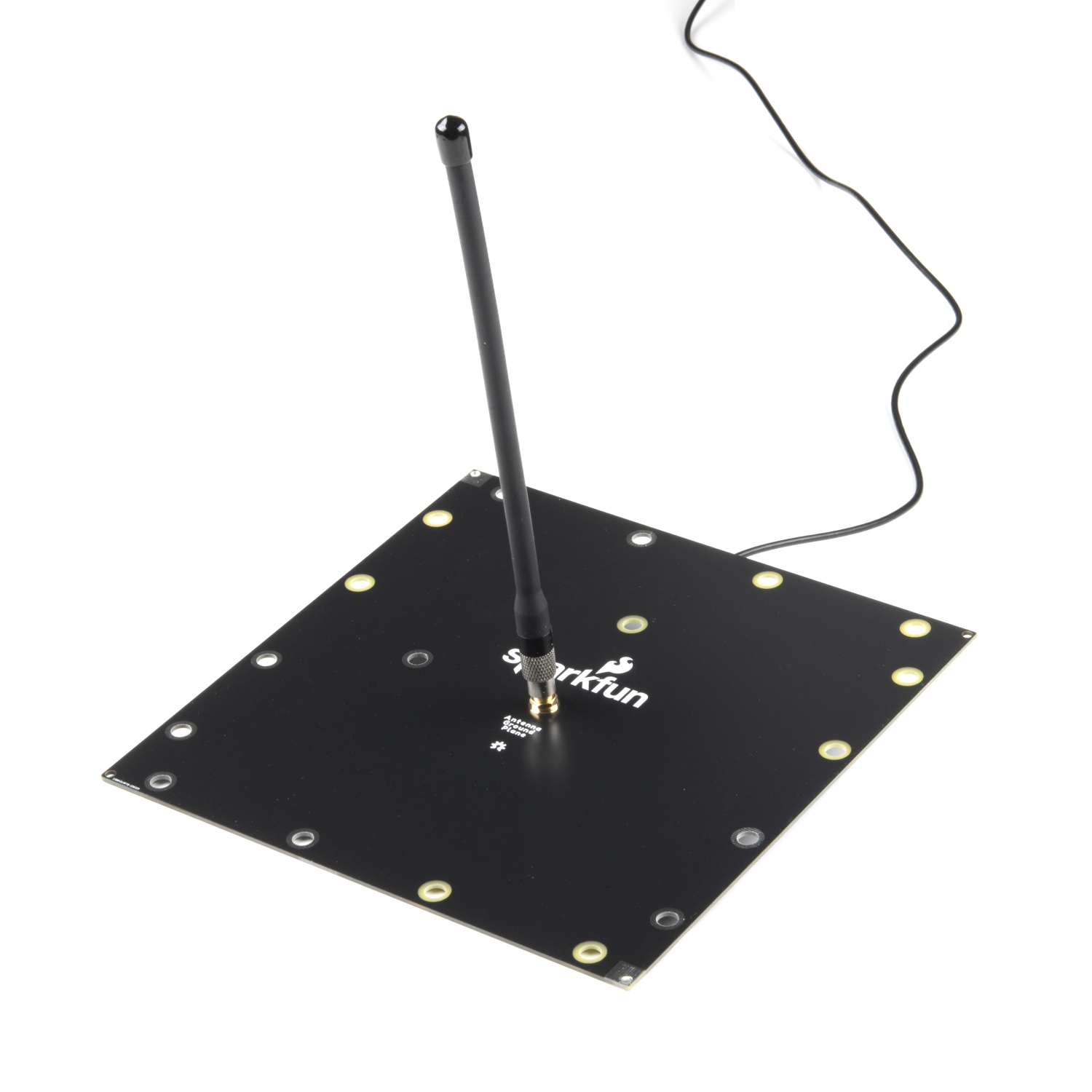

The ground plane has both grounded holes (holes with exposed tinned copper surround and through-hole plate) and plain through-holes (isolated). This allows you to connect the ground plane to any surrounding metalwork, or not, depending on your needs.
For best results, place the VHF antenna and ground plane at least 1m above the ground, or any solid surfaces.
The exposed finish is standard lead-free Hot Air Solder Levelled (HASL) plating. It will tarnish over time. You may wish to lacquer the board, with standard automotive spray lacquer, for longevity.
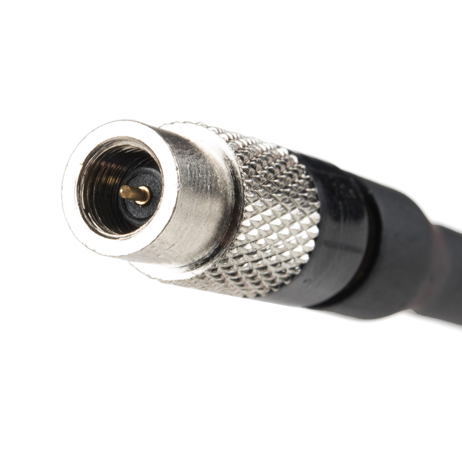
If you are using your own cables, check the SMA connector polarity. The Swarm antenna is standard polarity, not "RP" (Reverse Polarity):
SMA Male to SMA Female - 10m (RG174)
CAB-17495Hardware Hookup - USB
Once you've assembled the breakout and connected the antennas, connecting via USB is as simple as plugging in a USB cable!
Once USB is connected, the LEDs on the modem will indicate its status:
- Green:
- During the bootup sequence, the green LED will be on solid for 3 seconds.
- During normal operation after bootup and before shutdown, the green LED will blink 100ms every 5 seconds while the Modem is powered on. This is a “heartbeat” indication that the Modem is working as expected.
- Red:
- After power is applied until the Modem begins booting, the red LED will be on solid for 10 seconds.
- After bootup and while the Modem is acquiring a GPS fix, the red LED will flash quickly until a valid GPS fix has been found. Then the red LED will shut off during normal operation.
- After waking up from sleep, and before a fresh GPS fix has been acquired, there will be a single red LED flash every 5 seconds (following the green LED flash) until a fresh GPS fix has been found. Then the red LED will again shut off during normal operation.
- During the shutdown sequence, the red LED will be on solid until 3.3V power is removed from the board.
- Blue:
- The blue LED will be on solid when the Modem is actively receiving from a Swarm satellite.
Python User Interface
We've written a Python3 PyQt5 GUI (Graphical User Interface) to let you get up and running with the M138 modem. You can find the source code and executables in the dedicated GUI repo on GitHub.
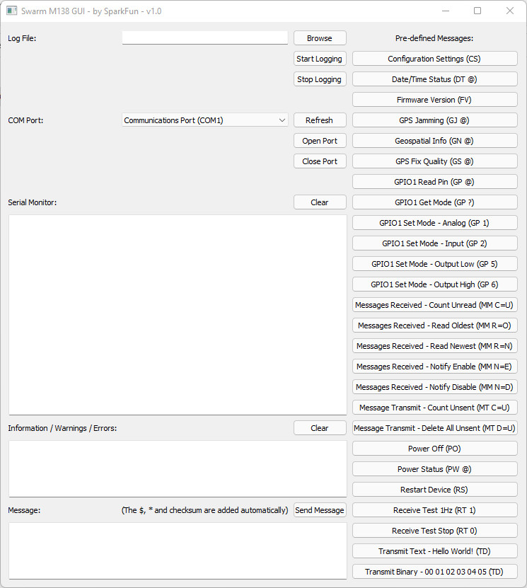
You will find full installation instructions in the repo.
Don't panic! The GUI will take a few seconds to open. Select the correct port from the drop-down list, click Open Port and away you go!
Click any of the pre-defined message buttons to send that message to the modem. Or enter your own message in the Message window and click Send Message to send it.
The modem message interface uses the same format as NMEA GNSS messages. They always start with a dollar and end with an asterix and a two character checksum. To make life easy, the GUI adds the $, * and checksum characters automatically. You do not need to include those!
The Modem manual contains the full list of modem commands and messages.
You can test the communication interface by pressing the “Configuration Settings (CS)” button. The Modem’s Device ID and Name will be displayed on the serial monitor in the format:
$CS DI=<dev_ID> ,DN=<dev_name>*xx
The next step is to place the device in an outdoor location with a clear view of the sky, away from any sources of RF noise. Once the device is set up outdoors, use the “Receive Test 1Hz (RT 1)” predefined message in the Python3 GUI to measure the background RSSI. The background RSSI measurements will be updated once every second and represent the noise floor in the testing environment. The measured background RSSI value should be between -95 and -105 dBm for reliable communication on the network. A lower, more negative, value is preferred.
The Modem will not be able to reliably communicate with the satellites if the reported background RSSI value is > -93 dBm. Try moving the device to a different testing location to observe how the measured value changes.
After confirming that the background RSSI is within the specified range, the next step is to queue some message packets on the Modem for transmission. The quickest way to queue messages for transmission is to use the predefined messages in the GUI shown at the bottom of the list. The message packets will be queued for transmission for a default hold time of 48 hours after which they will be discarded if not transmitted.
The message packet hold time is user configurable for each transmission command. Please refer to the Swarm M138 Modem’s Product Manual for more information, and for a full description of available commands.
The queued transmission packets will be transmitted when a satellite passes over the device’s location and beacons the Modem. The next satellite pass over your location can be predicted using the Swarm Satellite Pass Checker. There is also a YouTube video available that describes the pass checker’s functionality in more detail available here.
To know if a satellite is attempting to communicate with the Modem, ensure that the “Receive Test 1Hz (RT 1)” command is enabled. Observe the serial monitor for satellite beacons in the format:
$RT RSSI=<rssi_sat>,SNR=<snr>,FDEV=<fdev>,TS=<time>,DI=<sat_id>*xx
The Modem will attempt to transmit queued message packets after receiving the satellite beacons. Each successful transmission will be acknowledged by the satellite and will be displayed on the serial monitor in the format:
$TD SENT RSSI=<rssi_sat>,SNR=<snr>,FDEV=<fdev>,<msg_id>*xx
The transmitted data packet will then be visible on the Swarm Hive shortly after transmission.
Hardware Hookup - Breakout Pins
Want to connect the Breakout to your Arduino microcontroller board? You can absolutely do that too!
By default:
- The modem TXO breakout pin is connected to the CH340 RXI via a split pad jumper
- Likewise, the modem RXI is connected to CH340 TXO
You will need to open the jumper links on the back of the board when connecting the TXO and RXI pins to an Arduino board.
You will probably need: break away headers and jumper wires. 2-pin jumpers will be useful for re-linking the CH340 connections later.
Connect:
- GND to GND / 0V on your Arduino board
- VIN to 5V on your Arduino board
- It is possible to connect VIN to 3.3V if your Arduino board can deliver enough current when the modem transmits
- Please see Current Draw below for more details.
- TXO to the Serial / UART RX input on your Arduino board
- RXI to the Serial / UART TX output on your Arduino board
The TXO and RXI signals are 3.3V.
Software Setup
Our Swarm Arduino Library makes it easy to get up and running with Swarm.
If you are new to Arduino and the IDE, this guide will get you up and running:
Installing Arduino IDE
If you haven't installed an Arduino Library before, this is the guide you need:
Installing an Arduino Library
- Install the Arduino IDE
- Click on Tools\Manage Libraries... to open the library manager
- In the search box, type SparkFun Swarm
- Click the Install button to install the library
Alternatively, you can grab the library directly from GitHub or can download it as a zip file by clicking the button below:
Arduino Example: Get Firmware Version
The SparkFun Swarm Satellite Arduino Library contains a full set of tried and tested examples which will run on almost all Arduino boards (RAM permitting).
The code below is a stripped-down version of Example3_getFirmwareVersion. Copy and paste the code into a new window in the Arduino IDE:
language:c
#include <SparkFun_Swarm_Satellite_Arduino_Library.h> // http://librarymanager/All#SparkFun_Swarm_Satellite

SWARM_M138 mySwarm;

#define swarmSerial Serial1 // Use Serial1 to communicate with the modem. Change this if required.

void setup()
{
  Serial.begin(115200);

  if (mySwarm.begin(swarmSerial) == false) // Begin communication with the modem
  {
    Serial.println(F("Could not communicate with the modem. Please check the serial connections. Freezing..."));
    while (1)
      ;
  }

  char *firmwareVersion = new char[SWARM_M138_MEM_ALLOC_FV]; // Create storage for the configuration settings

  mySwarm.getFirmwareVersion(firmwareVersion); // Get the firmware version

  Serial.print(F("The firmware version is: "));
  Serial.println(firmwareVersion);

  delete[] firmwareVersion; // Free the storage
}

void loop()
{
  //Nothing to do here
}
Save the file and click on the Upload button to upload the example onto your board.
Open Tools\Serial Monitor to see the modem firmware version.
Check that the baud rate is set to 115200.
Message Transmit, Receive and Pass-Prediction
Message transmit via Swarm is a little different to (e.g.) the Iridium satellite network.
The Swarm satellite constellation is increasing rapidly, but is not yet complete. There may be times when there are no satellites overhead to receive your message. If you queue a message for transmission during one of these times, the message is stored in the modem and transmitted during the next satellite pass. If you monitor the responses in the GUI or via the Arduino Library examples, you will see a $TD SENT notification when each message is transmitted. You can monitor how many unsent messages are still in the queue via the $MT C=U message.
There are two ways to predict the next satellite pass:
- Via the online Swarm Pass Checker
- Or by using the pass prediction examples in our Arduino Library
- The pass prediction code downloads the Swarm Two Line Element orbit parameters from CelesTrak
- Cross-checks these with the Swarm Pass Checker
- Produces a list of known 'good' satellites for your location
- The TLE orbit parameters are stored on microSD card for use offline (once downloaded, you do not need an Internet connection to perform a prediction)
- If you want to, you could send updated TLEs to your remote Swarm-enabled equipment, via Swarm message, so it can refine its pass predictions!
- The pass prediction examples were written for the SparkFun Thing Plus C - ESP32 WROOM: they use the ESP32's WiFi connection and the on-board microSD socket to store the TLE data
- You can adapt the examples to work on other WiFi and microSD capable boards, such as the: SparkFun MicroMod ESP32 Processor; and the SparkFun MicroMod Data Logging Carrier Board
Message receive via Swarm is significantly different to (e.g.) the Iridium satellite network.
"Mobile Terminated" messages are queued in the ground station and are passed to a satellite that is known to be passing over your modem's location. As a result, this can take tens of minutes, or hours in some circumstances, depending on your location and the timing of the satellite orbits. The message reception interval will decrease as the Swarm constellation increases.
If you are expecting to receive a message, make sure you have the Messages Received notifications enabled, via the $MM N=E message. That way you will receive a notification as soon as the message arrives. Alternatively, you can poll how many unread messages are in the modem's buffer using the $MM C=U message.
Current Draw
The peak current drawn by the modem, during message transmit, depends on the supply voltage:
| Supply Voltage | Sleep Current | Receive Current | Transmit Current |
|---|---|---|---|
| 3.3V | 80µA (Peak) | 26mA (Typ.), 40mA (Peak) | 850mA (Typ.), 1000mA (Peak) |
| 5.0V | 110µA (Peak) | 25mA (Typ.), 45mA (Peak) | 550mA (Typ.), 600mA (Peak) |
We strongly recommend powering the Breakout from 5.0V to reduce the peak current draw.
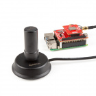
On Raspberry Pi boards, the USB sockets are powered directly by the (USB) Power In connector. You can connect the Swarm Breakout to Raspberry Pi using USB provided that your power supply can deliver enough current for both the RPi and the Swarm M138 (during transmit). The official Raspberry Pi 5.1V 2.5A (12.5W) power adapter is a good choice.
Troubleshooting
If you need technical assistance and more information on a product that is not working as you expected, we recommend heading on over to the SparkFun Technical Assistance page for some initial troubleshooting.
If you don't find what you need there, the SparkFun Forums are a great place to find and ask for help. If this is your first visit, you'll need to create a Forum Account to search product forums and post questions.
Resources and Going Further
For more information about the Satellite Transceiver Breakout - Swarm M138, check out the following links: