SparkFun Qwiic GPIO Hookup Guide
 El Duderino,
  Englandsaurus
Arduino Examples
The Qwiic GPIO Arduino Library has three examples split into single pin and port variants to demonstrate how to set up control the TCA9534 along with a fourth example demonstrating how to use the external interrupt capability. In this section we will go over those examples and highlight a few things to take note of when setting up your Qwiic GPIO in code.
#define Serial SerialUSB
This definition helps a ton when working with chip architectures that have multiple serial ports you need to call specifically instead of using a general
Serial calls. Simply update that definition with whichever serial port you want to use for serial prints via USB.
Example 1A: Write GPIO
A basic digital write example. Open Example 1A in Arduino by navigating to File > Examples > SparkFun Qwiic GPIO Arduino Library > Example1a-Write_GPIO. This example sets up GPIO 0 as an output and toggles it HIGH and LOW. The code starts up by initializing the Qwiic GPIO on the I2C bus on the default address and sets GPIO0 as an output:
language:c
myGPIO.pinMode(0, GPIO_OUT); //Use GPIO_OUT and GPIO_IN instead of OUTPUT and INPUT_PULLUP
Take note to use GPIO_OUT or GPIO_IN instead of the standard Arduino setup of OUTPUT and INPUT_PULLUP when setting the GPIO pin as an input or output. We use these alternates because the TCA9534's I/O pins default as an INPUT (pin mode = True) so GPIO_IN = true and GPIO_OUT = false are defined in the library to set the pin mode to avoid confusion. After we've set up GPIO 0 as an output, the code toggles it HIGH and LOW using digitalWrite(); every second and prints out the GPIO status via serial.
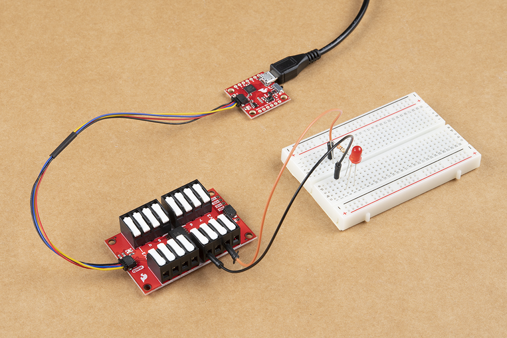
The demo circuit above shows a visual representation of GPIO 0 being toggled HIGH and LOW using an LED. If you want to control more pins, simply add another myGPIO.pinMode(); for whichever pin you want to use to set it as an output and then control it using myGPIO.digitalWrite();.
Example 1B: Write GPIO - Port
This version of writing to the Qwiic GPIO controls the entire port (all eight GPIO pins). In order to set up the port we need to define the number of GPIO pins we are using as well as construct a boolean to define each pin as either an input or output. Since this example is for writing to the port, all eight pins are defined as outputs:
language:c
#define NUM_GPIO 8

bool currentPinMode[NUM_GPIO] = {GPIO_OUT, GPIO_OUT, GPIO_OUT, GPIO_OUT, GPIO_OUT, GPIO_OUT, GPIO_OUT, GPIO_OUT};
Along with the pin mode, we also need to define the initial state of each GPIO:
language:c
bool gpioConfig[NUM_GPIO] = {HIGH, LOW, HIGH, LOW, HIGH, LOW, HIGH, LOW}
With the GPIO port configured, the code initializes the Qwiic GPIO on the I2C bus and then alternates the state of each pin every second using a function specific to this example called flipGPIO();:
language:c
void flipGPIO()
{
    for (uint8_t arrayPosition = 0; arrayPosition < NUM_GPIO; arrayPosition++)
    {
        gpioConfig[arrayPosition] = !gpioConfig[arrayPosition];
    }
}
Example 2A: Read GPIO
Example 2A demonstrates how to read an individual GPIO pin on the TCA9534. It starts by setting up GPIO 0 as an input, reads its state and prints out whether it is HIGH or LOW via serial. Similar Example 1, GPIO 0 is set up but in this case is set as an input using pinMode(0, GPIO_IN);. The code then monitors the pin's state every 250ms and prints the state via serial. You can view the main loop below:
language:c
void loop() {
  bool gpioState = myGPIO.digitalRead(0);
  switch (gpioState) {
    case true:
      Serial.println("HIGH");
      break;
    case false:
      Serial.println("LOW");
      break;
  }
  delay(250);
}
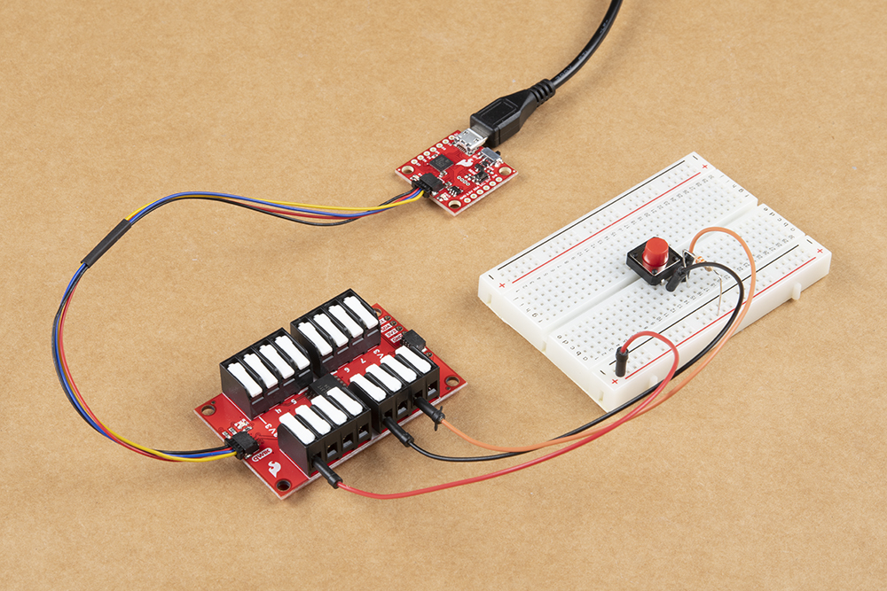
The example circuit pictured above demonstrates how to monitor an active HIGH input on the Qwiic GPIO by driving the selected I/O pin (in this case GPIO 0) LOW whenever the button is pressed.
Example 2B: Read GPIO - Port
Example 2B demonstrates how to read the entire GPIO port on the TCA9534. The code sets up all eight GPIO pins just like Example 1B using a boolean but this time all pins are set as inputs. We also need to set up a second boolean for the GPIO pin status due to how the port read register of the TCA9534 works:
language:c
bool gpioStatus[NUM_GPIO]
With the port set up and configured, we can move on to initializing the Qwiic GPIO on the I2C bus and start reading the status of the entire GPIO port. As the comment in the code below explains, in order to read from the port you can either return the full register value as an unsigned 8-bit integer or by passing an array of 8 booleans modified by the function that returns the status of each pin. The example defaults to the latter and sets up an array for the port read:
language:c
void loop() {
  //There are two ways to read from a port, either by returning the full register value as a uint8_t, or passing in an array of 8 boolean's to be modified by the function with the statuses of each pin
  uint8_t portValue = myGPIO.digitalReadPort(gpioStatus);

  Serial.print("uint8_t: ");
  Serial.println(portValue, BIN);
  Serial.print("Bool array: ");
  for (uint8_t arrayPosition = 0; arrayPosition < NUM_GPIO; arrayPosition++) {
    Serial.print(arrayPosition);
    Serial.print(": ");
    switch (gpioStatus[arrayPosition])
    {
      case true:
        Serial.print("HIGH");
        break;
      case false:
        Serial.print("LOW");
        break;
    }
  }
  Serial.println("\n");
  delay(100);
}
Example 3A: Inversion
Example 3A shows how to invert the signal polarity of an input on the Qwiic GPIO. Polarity inversion only works on pins configured as an input so first we set the pin mode and then we invert the polarity. Input pins default to active HIGH so inverting it changes it to active LOW. Below you can see the setup required for pin inversion:
language:c
myGPIO.pinMode(0, GPIO_IN);
myGPIO.invertPin(0, INVERT);
Once we have set up the pin as an input and inverted the polarity the main loop reads the status of the pin every 100ms:
language:c
void loop() {
  bool status = myGPIO.digitalRead(0);
  switch (status)
    {
      case true:
        Serial.println("GPIO 0: HI");
        break;
      case false:
        Serial.println("GPIO 0: LO");
        break;
    }
  delay(100);
}
Example 3B: Inversion - Port
Example 3B, as you might expect by now, exhibits how to invert the entire port on the Qwiic GPIO. The code starts as the other port examples do by defining the number of pins and setting the pin mode of all pins on the port. It then inverts half of the pins' polarity using a second boolean. The setup can be seen below:
language:c
#define NUM_GPIO 8

bool currentPinMode[NUM_GPIO] = {GPIO_IN, GPIO_IN, GPIO_IN, GPIO_IN, GPIO_IN, GPIO_IN, GPIO_IN, GPIO_IN};

bool inversionStatus[NUM_GPIO] = {INVERT, INVERT, INVERT, INVERT, NO_INVERT, NO_INVERT, NO_INVERT, NO_INVERT};
The main loop is identical to Example 2B - ReadGPIO - Port and prints out the state of the port register using an unsigned 8-bit integer.
Example 4: Interrupt
#define INTERRUPT PIN 13 to the selected pin. If you are not familiar with using processor interrupts on a microcontroller, this tutorial will help you get started.Example 4 demonstrates how to use the interrupt pin on the TCA9534 when any input pin registers a change. The interrupt pin is active LOW and will return to HIGH once the input register is read. We've broken the INT pin out to a latch terminal so you can connect a wire to that terminal and tie it to the interrupt-capable pin on your microcontroller. If you prefer, the INT pin is also broken out to a PTH pin you can solder to. Whichever option you choose, connect the interrupt pin on your Qwiic GPIO to D13 on your Arduino (assuming you are using an Uno/RedBoard).
The code starts similarly to our other Port examples by defining the number of GPIO pins and setting their pin status. Along with the GPIO pins, we define the interrupt pin on our microcontroller. You can view the pertinent bits of this code below:
language:c
#define NUM_GPIO 8

#define INTERRUPT_PIN 13

bool currentPinMode[NUM_GPIO] = {GPIO_IN, GPIO_IN, GPIO_IN, GPIO_IN, GPIO_IN, GPIO_IN, GPIO_IN, GPIO_IN};

bool gpioStatus[NUM_GPIO];

bool dataReady = true;
With everything defined, the setup initializes the Qwiic GPIO on the I2C bus, sets the interrupt pin on the microcontroller as an input, "primes" it by writing it HIGH and tells our microcontroller to treat it as an interrupt:
language:c
pinMode(INTERRUPT_PIN, INPUT_PULLUP);
digitalWrite(INTERRUPT_PIN, HIGH);
attachInterrupt(digitalPinToInterrupt(INTERRUPT_PIN), ISR, FALLING);
Now that our interrupt pin is configured the code monitors the GPIO pins' statuses and any time the status changes, the interrupt pin on the Qwiic GPIO will be driven LOW. You can view the entire loop and ISR function below:
language:c
void loop() {
  if (dataReady) {
    myGPIO.digitalReadPort(gpioStatus);
    for (uint8_t arrayPosition = 0; arrayPosition < NUM_GPIO; arrayPosition++) {
      Serial.print(arrayPosition);
      Serial.print(": ");
      switch (gpioStatus[arrayPosition])
      {
        case true:
          Serial.print("HI ");
          break;
        case false:
          Serial.print("LO ");
          break;
      }
    }
    Serial.println();
    dataReady = false;
  }
}

void ISR() {
  dataReady = true;
}
That wraps up the Arduino examples but if you would prefer to use Python instead with a different development board or single-board computer like the Raspberry Pi, read on to the next two sections where we'll detail how to use the Qwiic GPIO Python Package.