SparkFun Qwiic GPIO Hookup Guide
 El Duderino,
  Englandsaurus
Hardware Assembly
The Qwiic system makes connecting the Qwiic GPIO to your chosen microcontroller a breeze. All you need to do is connect your Qwiic GPIO to your chosen development board with a Qwiic cable or adapter cable. If you would prefer to not use the Qwiic connectors, you can connect to the 0.1" header pins broken out on the side of the board.
If you prefer to use the PTH pins broken out on the Qwiic GPIO you will need to solder to them. For a temporary connection for prototyping, these IC Hooks are a great option to make that connection. For users not familiar with through-hole soldering take a look at this tutorial:
How to Solder: Through-Hole Soldering
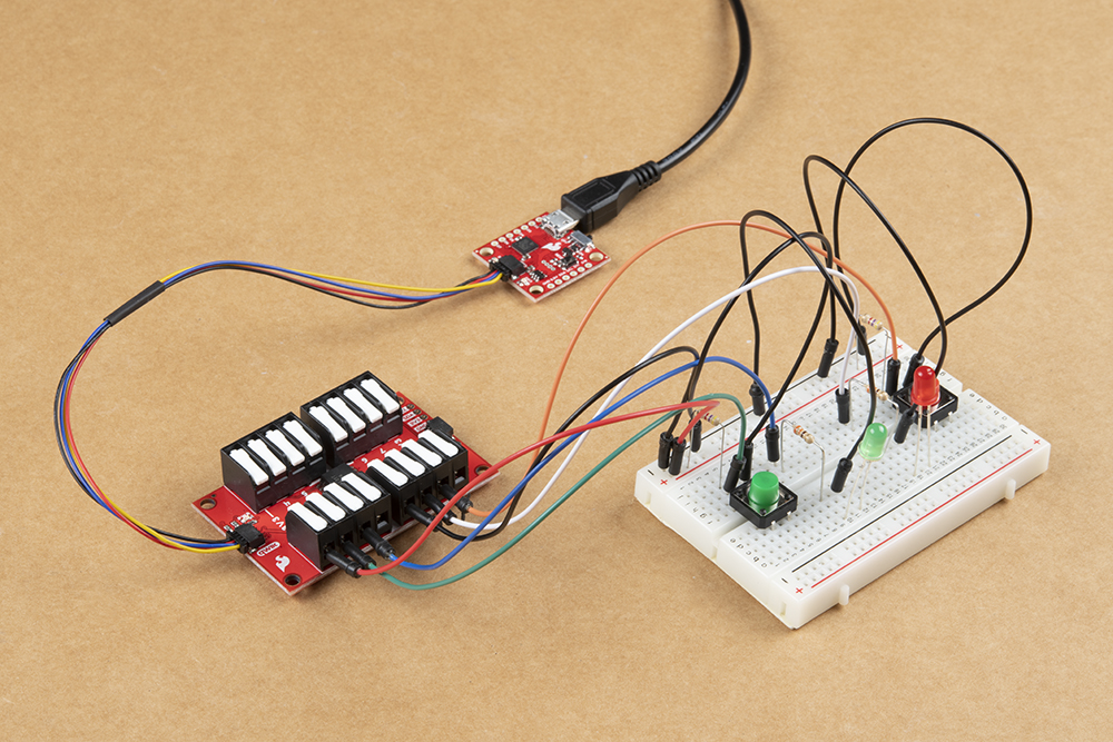
Connecting peripherals to the GPIO is simple as well with the latch terminals. If you are using hook-up wire, make sure you've stripped the end, insert it into the appropriate terminal (making sure it is "open") and then press down on the latch terminal firmly to secure the wire in place. Depending on how you intend to use the I/O pin you'll want to connect your other wire to either a 3.3V or Ground pin. For demonstration purposes, we're using LEDs and buttons to act as our inputs and outputs (respectively).
With the Qwiic GPIO circuit assembled and connected to your microcontroller it's time to get some code uploaded and start controlling the extra I/O pins via I2C!