SparkFun PIR Breakout Hookup Guide
 El Duderino,
  Englandsaurus
 Introduction
Looking to add some motion detection to a project you are working on? The SparkFun PIR Breakout - 170uA (EKMC4607112K) and SparkFun PIR Breakout - 1uA (EKMB1107112) might be just the thing! These breakouts use two versions of the EKM-series PIR sensors from Panasonic® to offer low profile motion-sensing options for both battery powered and continuously powered applications.
Passive Infrared (PIR) sensors do not return specific distance data like distance sensors. Instead, PIR sensors measure IR light coming from objects to detect motion in their field of view making them perfect for motion-sensing applications such as turning devices like lights, cameras, motors, etc. on automatically. The PIR sensors on these breakouts output a digital signal whenever a moving object is detected in the sensing area. That signal can be monitored by a microcontroller to trigger action on a connected device like those mentioned above.
Required Materials
In order to follow along with this tutorial you'll need a few items along with your PIR Breakout. First, you'll need a microcontroller or Single-Board Computer (SBC) like a Raspberry Pi or Jetson Nano to monitor the PIR's signal:


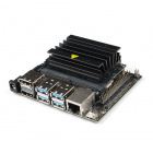
NVIDIA Jetson Nano Developer Kit (V3)
DEV-16271You also may need some wire and headers to connect your breakout to your microcontroller. Depending on your intended connections, you may want to use one or more of the following connection and wire options:


Lastly, for easier testing of the range and detection area of your PIR Breakout installation, you may want to have an LED or sound output like a buzzer to act as an indicator for when the sensor detects motion.
Recommended Tools
We recommend soldering to the PTH header on the PIR Breakouts for the best connection. If you do not have soldering tools and accessories, take a look at the following options:


Weller WLC100 Soldering Station
TOL-14228Suggested Reading
PIR sensors are pretty straight-forward and a great entry point for novices with embedded electronics and sensors but if you aren't familiar with the concepts covered in the tutorials linked below, you may want to take a look through them before getting started with the SparkFun PIR Breakout:
How to Solder: Through-Hole Soldering
What is an Arduino?
Logic Levels
Raspberry Pi 4 Kit Hookup Guide
Hardware Overview
In this section we'll cover the characteristics and features of the PIR sensors on these breakouts.
Panasonic EKM-Series PIR Sensors
The EKMC4607112K and EKMB1107112 from Panasonic are low-profile PIR sensors ideal for things like motion-activated lights, cameras or other electronics. Applications include automatic lighting for energy conservation, motion-activated security or trail cameras or maybe something fun like a homemade convenience store chime (complete with a 100th customer celebration!). The EKMC4607112K works best in a continuous power installation and has slightly better sensing performance than the EKMB1107112 which is best suited for battery and low-power installations.
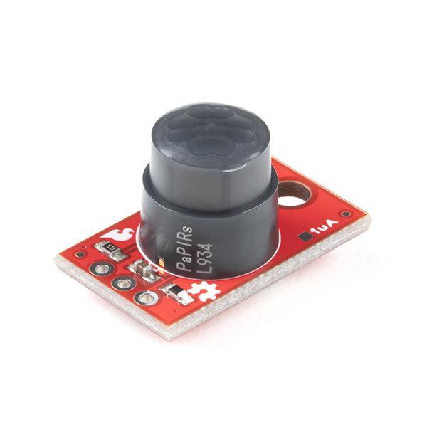
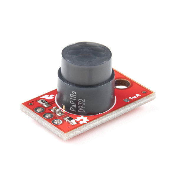
 |
 |
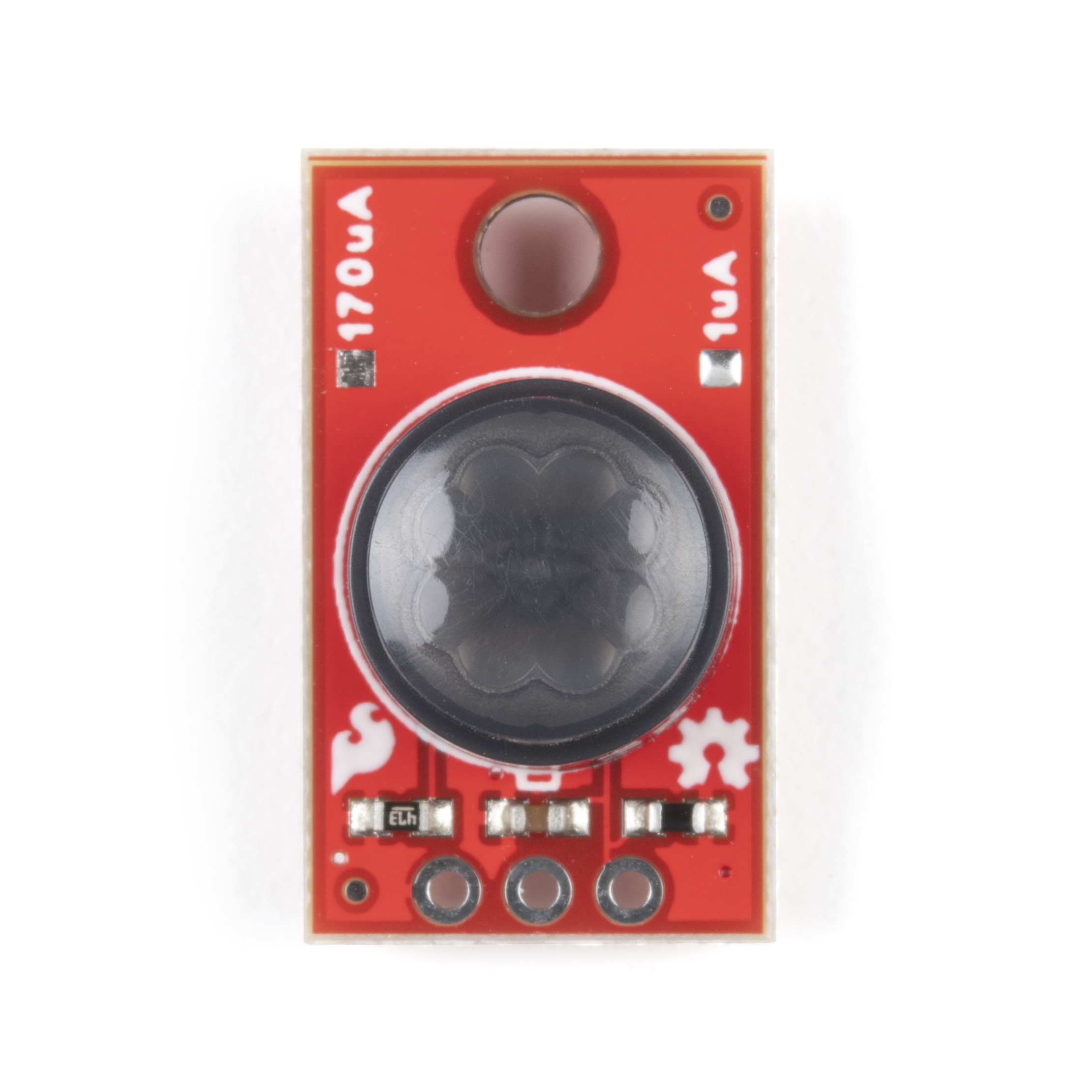
| SparkFun PIR Breakout - 1µA Front. | SparkFun PIR Breakout - 1µA Back. |
On each breakout we've broken the sensor's three pins (3V3/VDD, Ground and OUT) to a standard 0.1"-spaced PTH header for users to solder to. Take note that the sensors share the same PCB design and the version (1µA or 170µA) is marked by the solder pads "North" of the PIR.
The two PIR sensors have very similar electrical and sensing characteristics with a few specific differences users will want to take note of prior to deciding which sensor is best for their situation. The tables below outline the Electrical and Detection Performance Characteristics to give users a basic overview. For a more detailed look at these two sensors, take a look at their respective specification sheets: EKMC4607112K & EKMB1107112 along with the Panasonic PIR Sensors - Product Brief (EKM-Series sensors are covered on page 8).
| Electrical Characteristics | |||||||
|---|---|---|---|---|---|---|---|
| EKMC4607112K | EKMB1107112 | ||||||
| Characteristic | Units | Min | Typ. | Max | Min | Typ. | Max |
| Operating Voltage | VDC | 3.0 | - | 6.0 | 2.3 | - | 4.0 |
| Current Consumption (Sensor Only) |
µA | - | 170 | 300 | - | 1[1] | 3 |
| Output Current | µA | - | - | 100 | - | - | 100 |
| Output Voltage | VDC | VDD-0.5 | - | - | VDD-0.5 | - | - |
| Circuit Stability Time (when voltage is applied) |
secs | - | - | 30 | - | 25 | 210 |
As we mentioned above, the sensing performances of the PIR Sensors are very similar with a few notable differences you'll want to be aware of to decide which one works best for your application. Also take note that PIR sensor performance can vary depending on the environment it is sensing.
Both the EKMC & EKMB have detection areas of 90° Horizontal and Vertical (±45°) and have 32 detection zones. The table below outlines their detection performance in relation to the background temperature:
| Detection Performance Characteristics | |||||
|---|---|---|---|---|---|
| EKMC4607112K | EKMB1107112 | Notes | |||
| Temperature Difference | Value | Temperature Difference | Value | Target Conditions | |
| Detection Range | 8°C (14.4°F) | up to 7m | 4°C (7.2°F) | up to 7m | 1. Movement speed: 1 m/s 2. Target concept is human body (Object size:Around700×250mm) |
| 4°C (7.2°F) | up to 5m | 2°C (3.6°F) | up to 5m | ||
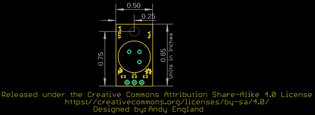
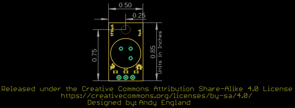
Board Dimensions
The SparkFun PIR Breakout measures 0.50" x 0.85" (12.7mm x 21.59mm) and has one mounting hole that fits a 4-40 screw.
Hardware Assembly
Assembling the PIR Breakout circuit is pretty straight-forward since the board only has three pins. Recommended setup requires some soldering so if you are not familiar with through-hole soldering or want a refresher, we suggest reading through this tutorial:
How to Solder: Through-Hole Soldering
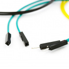
The demo circuit we'll assemble for the PIR Breakout uses a standard breadboard, M/M Jumper Wires and a SparkFun RedBoard Qwiic along with the SparkFun PIR and a set of breakaway male headers - right angle.
For permanent installations, we recommend soldering wire directly to the PIR Breakout to create a strong and stable connection to the sensor. For some tips on preparing and soldering wire, take a look at this tutorial:
Working with Wire
To start off, we break off three pins from the set of breakaway male headers and solder them to the PTH header on the PIR Breakout to have the sensor stand perpendicular to the breadboard for easy testing.

Next, we plug the sensor into the breadboard (users connecting directly to their microcontroller can ignore this step) taking care to orient it properly so the pins are not sharing the same rail. After the PIR is in place, select three jumper wires and connect the PIR's pins to the matching pins on the microcontroller. 3.3V to 3.3V, GND to Ground/GND and OUT to a digital I/O pin.
- EKMC4607112K: 3.0 to 6.0V
- EKMB1107112: 2.3 to 4.0V
The OUT signal from the SparkFun PIR can also be used as an external interrupt to trigger an interrupt event on a microcontroller. Users who wish to use the PIR as an external interrupt should note which digital I/O pins on their microcontroller are interrupt-capable and connect the PIR's OUT to one of those pins. For this example, we'll connect the OUT pin to a digital pin that is also interrupt capable: D2.

If you are using a Raspberry Pi or other SBC/development-board that uses Python as its primary programming language, follow the above assembly steps for the PIR and connect it to your Pi/SBC's GPIO header taking care to make the proper pin connections. Raspberry Pi users looking for a quick GPIO reference can find one here or you can use the pinout command from the GPIO Zero Python Library in the console to display the pinout there.
Arduino Examples
Now that our SparkFun PIR Breakout circuit is assembled it's time to upload some code to our microcontroller to interact with the sensor. We'll cover three examples in this section to demonstrate how to read the signal, stabilize it and use it as an external interrupt to trigger events on a microcontroller.
Example 1 - Simple Read with Debounce
This quick and dirty example monitors the PIR output signal on D2 and uses the built-in LED on the SparkFun RedBoard as a visual indicator whenever the PIR detects an object in it's field of view.
Copy the code below into a blank Arudino sketch, open the Tools menu to select your board (in our case, Arduino Uno) and correct Port and click the "Upload" button:
language:c
#define PIR_PIN 2   // PIR output on D2
#define LED_PIN  13  // LED to illuminate on motion
#define DEBOUNCE_TIME 750


void setup()
{
  Serial.begin(115200);
  // Set the PIR Output signal as an input for the microcontroller:
  pinMode(PIR_PIN, INPUT);

  // Configure the LED pin as an output
  pinMode(LED_PIN, OUTPUT);
  digitalWrite(LED_PIN, LOW); // Turn the LED off

  // Wait for 30 seconds for the PIR to stabilize after power on:
  Serial.println("Waiting 30 Seconds while PIR warms up");
  for (uint8_t seconds = 0; seconds < 30; seconds++)
  {
    Serial.println(seconds);
    delay(1000);
  }
  Serial.println("PIR Warmed up.");
}

void loop()
{
  // The PIR's output is active high
  int motionStatus = digitalRead(PIR_PIN);

  // If motion is detected, turn the onboard LED on and print an object was detected:
  if (motionStatus == HIGH)
  {
    Serial.println("Object Detected!");
    digitalWrite(LED_PIN, HIGH);
    delay(DEBOUNCE_TIME);
  }
  else // Otherwise turn the LED off and print All Clear:
  {
    Serial.println("All clear!");
    digitalWrite(LED_PIN, LOW);
    delay(DEBOUNCE_TIME);
  }
}
After uploading, open the serial monitor and set your baud to 115200 to see the serial data. The code will print out over serial any time the PIR detects motion in it' field of view and the D13 LED should illuminate.
Example 2 - Interrupt
The Interrupt Example shows how to set up the output signal from the PIR as an external interrupt to trigger an event on your microcontroller. This is particularly helpful for applications where you do not want to constantly poll the digital pin the PIR's output is connected to so you can run other loops in the background.
As we mentioned in the Hardware Assembly, this example assumes a SparkFun RedBoard/Arduino Uno is used and uses D2 as the interrupt pin. If you are using a different microcontroller, adjust the PIR_PIN definition to an interrupt-capable pin.
Copy the code below into a blank Arudino sketch, open the Tools menu to select your board (in our case, Arduino Uno) and correct Port and click the "Upload" button:
language:c
#define PIR_PIN 2 //Connect the output of the PIR to this pin
#define DEBOUNCE_TIME 750

bool pirStatus = false;
bool lastPirStatus = pirStatus;

void interruptRoutine() {
  pirStatus = digitalRead(PIR_PIN);
}

void setup() {
  Serial.begin(115200);
  pinMode(PIR_PIN, INPUT);
  attachInterrupt(digitalPinToInterrupt(PIR_PIN), interruptRoutine, CHANGE);

    // Wait for 30 seconds for the PIR to st abilize after power on:
  Serial.println("Waiting 30 Seconds while PIR warms up");
  for (uint8_t seconds = 0; seconds < 30; seconds++)
  {
    Serial.println(seconds);
    delay(1000);
  }
  Serial.println("PIR Warmed up. Starting readings");
}

void loop() {
  if (pirStatus != lastPirStatus) {
    if (pirStatus)
    {
      Serial.println("Object Detected");
    }
    else
    {
      Serial.println("Object Removed");
    }
    lastPirStatus = pirStatus;
  }
  delay(DEBOUNCE_TIME);
}
From here, you can modify the code so the interrupt event triggers whatever behavior you would like. If you find the interrupt is firing too often, modify the code to trigger only on detected events or by modifying the interrupt type to be either RISING or FALLING.
Python Example
Note: This example assumes you are using the latest version of Python 3. If this is your first time using Python or GPIO hardware on a Raspberry Pi, please read through our Python Programming with the Raspberry Pi guide and the Raspberry Pi GPIO Tutorial.
If you've assembled your SparkFun PIR Breakout circuit with a Raspberry Pi or other Python-based development board, we've written a quick example to demonstrate how to read the PIR's output.
Example Dependencies
In order to interface with your Pi's GPIO ports your user must be a member of the gpio group. The pi user is a member by default. Users with sudo privileges can add users manually using the following command:
language:bash
sudo usermod -a -G gpio <username>
Simple Read
This example demonstrates reading the SIG output from the PIR sensor using digital reads. Copy the code below into your preferred Python interpreter or into a blank text file and save it. If you are using an interpreter like Thonny, you can run it from there. Otherwise, open the terminal and run it by entering the following command: python3 FILENAME.py
language:python
import time
import RPi.GPIO as GPIO
import sys

#Pin Definition
pir_pin = 4

#Set up pins and set PIR signal as an input
GPIO.setmode(GPIO.BCM)
GPIO.setup(pir_pin, GPIO.IN)

def run_example():

    #Wait 30 seconds for the PIR to stabilize

    print ("Waiting 30 seconds for PIR to stabilize")
    for i in range(0, 30):
        print(i)
        time.sleep(1)

    print ("Device Stable. Starting readings...")

    #Start monitoring the PIR output. If an object is detected, print "Object Detected" otherwise print "All Clear"

    while True:
        if GPIO.input(pir_pin):
            print("Object Detected")
        else:
            print("All clear")
        time.sleep(1)

if __name__ == '__main__':
    try:
        run_example()
    except (KeyboardInterrupt, SystemExit) as exErr:
        print("\nEnding Example")
        sys.exit(0)
Troubleshooting
Hopefully by following the steps in this guide you've got your SparkFun PIR Breakout up and running monitoring motion and reporting data to your preferred microcontroller or single-board computer. In case you run into any issues we've outlined a few tips and tricks for testing the PIR here.
Hardware Check
Most common problems with the PIR Breakout revolve around the hardware connections. If your PIR Breakout is not powering on or your microcontroller/SBC cannot detect the output signal from the sensor, double-check your solder joints and your wiring to the microcontroller/SBC. The Hardware Checks section of our Troubleshooting Tips guide can help you diagnose any connection problems.
Detection Area/Field of View
The effective detection area of both the EKMC4607112K and EKMB1107112 is dependent on a variety of factors. The specifications for measurement range are based on a target concept (area of ~700×250mm) of a human body moving across two detection zones at a speed of 1m/s. The PIR senses objects best when moving across two detection zones on the horizontal (X) or vertical (Y) axes. The PIR may struggle to detect objects moving away or toward the PIR (along the Z axis) unless they also move along the other two axes.
Also note that background IR radiation can influence the PIR's ability to detect an object. The PIR can detect objects with a larger temperature difference from the background at a larger range. Refer back to the Hardware Overview section for specific ranges and temperature differences.
Take these detection limitations into consideration when selecting the mounting position of your PIR Breakout. Section 4-7 of the sensors' spec sheets (EKMC4607112K and EKMB1107112) show diagrams for optimal placement and object motion for sensing.
General Troubleshooting
If you need technical assistance and more information on this or another SparkFun product that is not working as you expected, we recommend heading on over to the SparkFun Technical Assistance page for some initial troubleshooting:
If you don't find what you need there, the SparkFun Forums are a great place to find and ask for help. If this is your first visit, you'll need to create a Forum Account to search product forums and post questions.
Resources and Going Further
That's all for this Hookup Guide! For more information about the SparkFun PIR Breakout take a look at the following links:
- Schematic (PDF)
- Eagle Files (ZIP)
- Dimensional Drawing (PNG)
- EKMC4607112K Datasheet (PDF)
- EKMB1107112 Datasheet (PDF)
- Panasonic PIR Motion Sensors - Product Brief
- Hardware GitHub Repository
Looking for more information on PIR sensors or for some inspiration on how to use your PIR Breakout in a motion-sensing project? These tutorials can help: