SparkFun gator:log Hookup Guide
 Englandsaurus
Hardware Overview
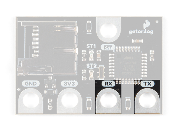
The gator:log consists of 5 pads for power, data, and an interrupt.
| Contacts | Direction | Description |
|---|---|---|
| GND | N/A | Ground: Reference voltage and ground loop. |
| 3.3V | In | Power: Provides 3.3V to the board. |
| RX | In | Data and commands are transmitted to the gator:log from an external microcontroller (i.e. micro:bit). |
| TX | Out | Data can be read from an SD card on the gator:log by an external microcontroller (i.e. micro:bit). |
| RST | In | Pin goes high or low based on if the gator:log needs to be initialized. |
Power
The specified operating voltage for the ATmega328 is between 1.8V - 5.5V. For use with the gator:bit (v2) and micro:bit, you should provide 3.3V through the 3V3 and GND pads to keep the logic levels consistent.

ATmega328P
The heart of the gator:log is an ATmega328P microcontroller. The ATmega328P is used to handle the incoming data and store it on an µSD card. It is also used to handle all the file directory, organization functions available for the gator:log. For the most part, users just need to be aware that the RST pad must be connected in addition to the other pads.
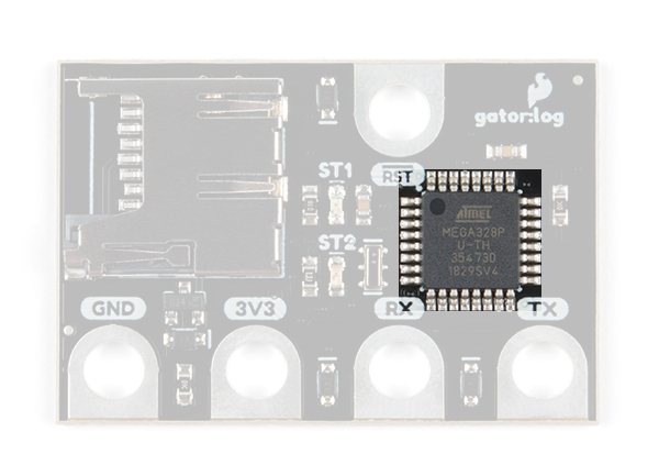
Here are some of the characteristics of the ATmega328P microcontroller from the datasheet:
| Characteristic | Range |
|---|---|
| Operating Voltage | 1.8V to 5.5V |
| Current |
Idle: approx. 25 mA (avg.) Peak: approx. 35mA (w/ status LEDs flashing) |
| Storage | SD Card |
| Input Channels | 1- Serial Data |
| Speed |
Input: Serial Data Output: Serial Data |
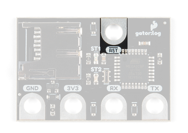
Reset Pad
The reset pad is used to initialize the begin function for the ATmega328P microcontroller. This pin must be connected when the gator:log is initialized to function properly.
What is a Data Logger?
A data logger is a device that records data over time, usually from an instrument or sensor. Most often, they are low power, use a microprocessor, include (internal or external) data storage options, contained in a compact enclosure, and are battery powered. Generally, data loggers are useful for collecting data from remote locations for extended periods of time. In s, these devices will include a renewable power source for self sufficiency and may have a remote data link when it is not be feasible to constantly drive out to change batteries and/or data storage.
Below is a list of a few examples of data logging applications:
- Weather Stations and Buoys
- Monitoring Agricultural Conditions
- Road Traffic
- Wildlife Conservation
- Building Monitors (i.e. for Power/Water usage and HVAC Efficiency)
- Monitoring for Athletes Performance (Biosenors)
For more details on data logging applications, check out these online resources:
- Sensor Fusion and Smart Sensor in Sports and Biomedical Applications
- Data loggers reveal migration routes
- Monitoring Wetlands with Data Loggers:A Best Practices Guide (Example of a Commercial Data Logger Setup)
- Data Logger and Remote Monitoring System for Multiple Parameter Measurement Applications
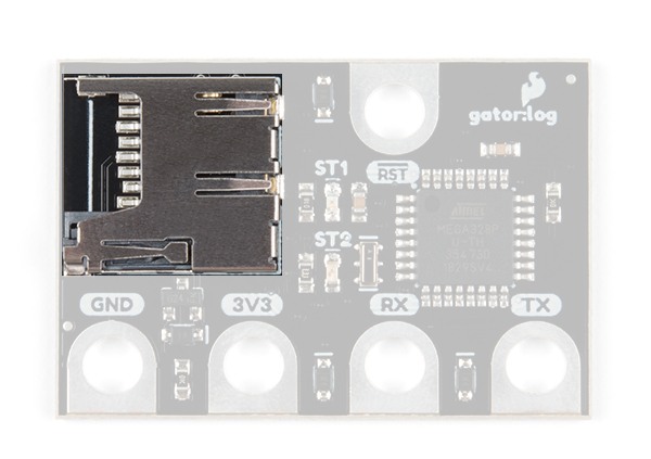
µSD Card Slot
A µSD (micro SD) card slot is available to for a µSD card, which is needed to store the data sent to the gator:log. The gator:log uses the SPI pins of the ATmega328P to send data to the SD card from a temporary buffer. In most cases, users only need to consider the recording time of the gator:log, know that the µSD card requires proper formatting, and be aware of the restrictions on the SD cards that are compatible with the gator:log, which are laid out in the table below.
| Characteristic | Range |
|---|---|
| Style | µSD card (microSD) |
| Type |
SD (SDSC) SDHC |
| Class | ≥4 |
| Capacity | 64MB to 32GB |
| Format | FAT16 or FAT32 |
Although, many users may already have a few SD cards lying around, the characteristics laid out in the table are known to be compatible with the gator:log. Be aware that using SD cards that fall outside of these restrictions are not guaranteed to work. If you aren't sure about the style or type of SD card you have, please check out this Wikipedia article on SD cards for more details.
Spring-Loaded Locking Mechanism: Once the SD card is placed in the slot, push in the card once. You should hear a soft click when the card is locked into place. To unlock or release the card, push the card in again. You should hear another click when it unlocks and the card will pop out. The card should slide out easily; if you feel resistance pulling out the card, it is probably still locked in place. Do NOT try to pry or force the SD card out of the slot, this will damage the locking mechanism and render the gator:log useless.
Calculating Data Usage
For most users, we recommend checking out our 1GB SD card. In most cases, this should hold enough data for a few sensors (depending on the amount of data you are storing and how quickly you are sampling that data).
Example Case:
- Our 1GB SD card has about 970MB of storage capacity
- Recording from 10 sensors
- Each sensor sends 20 characters of data
- Sampling rate of 1 ms
or
At 4850 seconds, that gives you about 1.3 hours of recording time. Now 1 ms is a pretty high data sampling rate, if you reduce that to 10 ms (or 100 times per second) and your recording time increases to about 13.5 hours.
If users need a longer recording time, they can change to an SD card with a higher storage capacity, change how often data is recorded, decrease the number of sensors used, or reduce the amount of characters stored per data set.
Status Indicator LEDs
There are two status LEDs on the gator:log to help with troubleshooting.
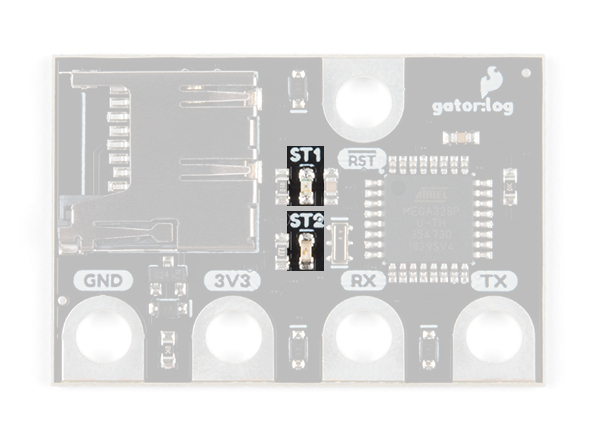
ST1 (Blue)
This blue indicator LED is attached to pad 5 of the ATmega328P. Mostly, users only need to be aware that this LED blinks when serial communication is functioning (i.e. data is being sent from the micro:bit to the gator:log).
ST2 (Green)
This green LED is connected to the SPI clock line on the ATmega328P. Mostly, users only need to be aware that this LED only blinks when the when the gator:log is recording data to the µSD card.
Note: If you are only sending short bursts of data, the green ST2 LED will be a lot more dim compared to the blue ST1 LED. You may need to cover it with your hands to see the LED blink clearly.
Serial Connection
Serial is an asynchronous communication protocol used to transfer data between devices. It is a 2-wire connection consisting of RX (receiving data in) and TX (transmitting data out). It's important to know that the RX and TX labels are with respect to the device itself. So the RX from one device should go to the TX of the other, and vice-versa.