SparkFun Arduino ProtoShield Hookup Guide
 bboyho
Hardware Overview
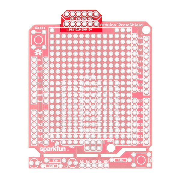
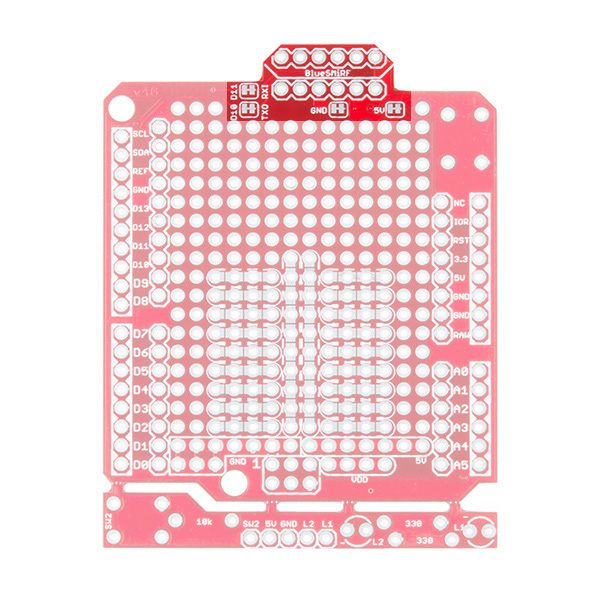
There is a lot going with the ProtoShield so it is useful to know what side we are referencing when soldering components to the board. We will refer to the top side based on the board's name on the upper right hand corner. The bottom will be the side with the jumpers.
 |
 |
| Top View | Bottom View |
Stackable Headers for Arduino Uno R3 Footprint
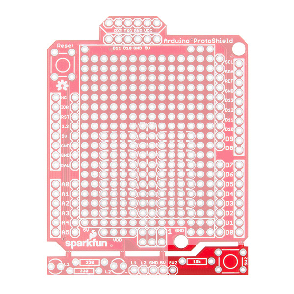
The Arduino ProtosShield is based off the Arduino R3's footprint. Headers can be installed on the pins located closest to the edge of the board. You will notice that the location of the headers are highlighted in a rectangular silkscreen. For those using the stackable headers included in the kit, make sure to insert the header from the top side and solder from the bottom.

These pins are also broken out on the other side of its labeling. You will notice that the 1x10 header on the upper right side of the board is slightly offset from the Arduino R3 footprint. Don't worry, this was intentional so that you can place the board on a standard breadboard!
Prototyping Area
Next up is the sea of plated through holes. Look at all that great space for prototyping projects!
Solderless Mini-Breadboard
Do you have a small circuit on a mini-breadboard connected to your RedBoard or Arduino Uno? The ProtoShield has a spot to place a mini-breadboard on top to keep everything together. Peel the adhesive off the mini-breadboard, align it to the silkscreen, and stack it on!
Solderable-Like Breadboard
Once you are done prototyping your circuit on the mini-breadboard, there is an option to solder the circuit directly to the board for a more secure connection. The bottom half of this area was designed with a breadboard in mind. You will not notice too much on the top side. Flip the board over and you will see open jumper pads between each through hole to make a connection like a breadboard. Once you add a component, simply add a solder jumper between holes to make a connection. For those that prefer the standard prototyping pads, we left the other side as is.
") |
") |
| Solderable-Like Breadboard (Top View) | Solderable-Like Breadboard w/ Open Jumpers (Bottom View) |
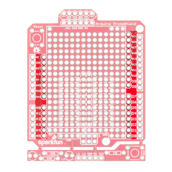
ICSP (MISO, MOSI, and SCK NC)
Need to access the Arduino's ICSP pins? The pins are broken out if you do not want to remove the shield every time you need the ICSP pins or if you decide to stack another shield on top of the ProtoShield. You will need add two 1x3 stackable headers.

Additionally, there may not be enough room for a mini-breadboard if you decide to add 1x3 stackable headers to the ICSP pins and then stack an additional shield on top. You will need to go with a lower profile by soldering the circuit with wires to the ProtoShield.
Power
There are a few locations along the outside of the board for power and ground. Let's focus on the power rails in the prototyping area.
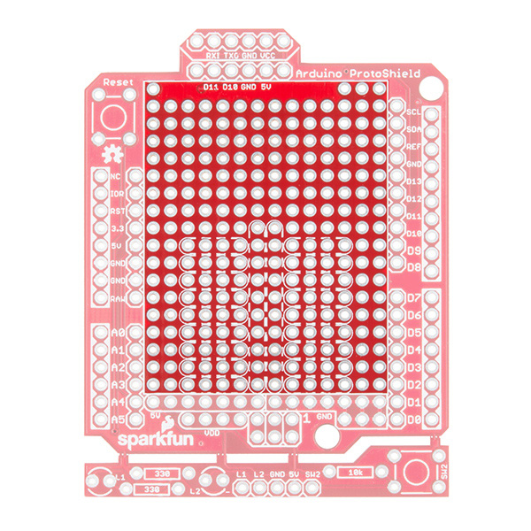
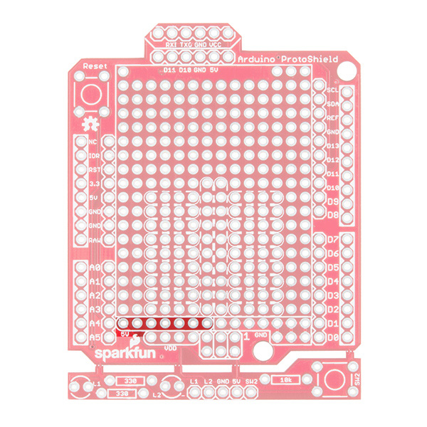
5V Rail
Just below the silkscreen for the mini-breadboard is a 5V rail. This is connected to the 5V pin from your Arduino.
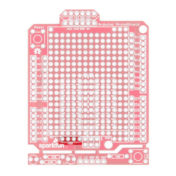
VDD Rail (NC)
Need a different voltage? We squeezed a VDD rail just below. It is currently not connected to anything. We left it up to the user to connect to Arduino's 3.3V pin or another regulated voltage (i.e. 2.8V or 1.8V).
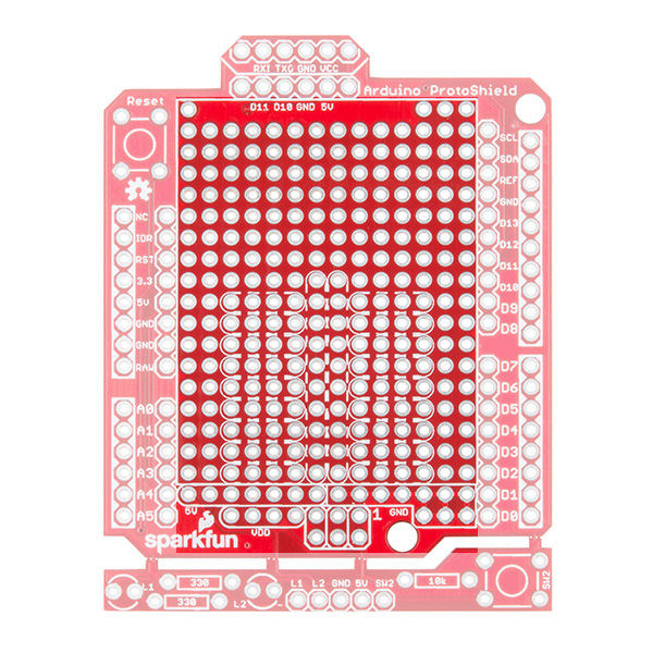
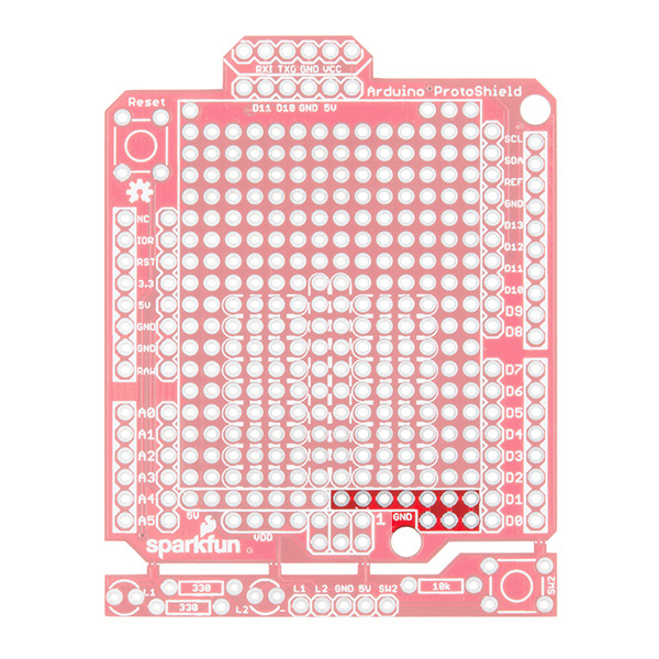
GND Rail
Need to ground more circuits? There are few more ground connections on the board as indicated by the image below.
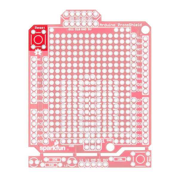
Reset Button
Stacking a shield on an Arduino can make it hard to reset the microcontroller. Like other Arduino shields, the reset button has been rerouted on the ProtoShield.
Software Serial UART Port
The SparkFun Arduino ProtoShield breaks out a software serial UART port. The pins are arranged in such a way as to connect to our BlueSMiRF if you decide to go wireless.
If you decide that you want to connect a different serial UART device (i.e. a UART-to-serial device like the FTDI Basic Breakout) or use different pins for serial, we added closed jumpers on the back. Simply cut the traces and reroute the connection by adding wires to the headers.
Oh Snap! ProtoSnap-able Prototyping Hardware
The board includes prototyping hardware that is based on the ProtoSnap design. When you are finished testing and want to use bigger components, simply snap off the bottom of the board using pliers.

3mm LEDs (NC)
When viewing the board from the top, there are two locations for 3mm LEDs and their 330Ω current limiting resistors.
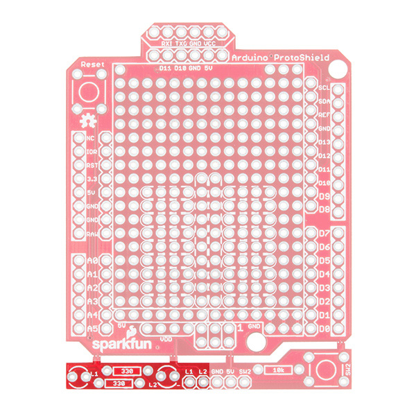
Momentary Pushbutton (NC)
There is a spot for a momentary pushbutton and 10kΩ pull up resistor on the other side of the LEDs.