How to Work with Jumper Pads and PCB Traces
 bboyho
 Introduction
Handling PCB jumper pads and traces is an essential skill. In this tutorial, you will learn how to cut a PCB trace and add a solder jumper between pads to reroute connections. You will also learn how to repair a trace with the green wire method if a trace is damaged.
Suggested Reading
If you aren’t familiar with the following concepts, we recommend checking out these tutorials before continuing.
How to Solder: Through-Hole Soldering
PCB Basics
What is a Circuit?
How to Use a Multimeter
Required Materials
To follow along with this tutorial, you will need the following materials:


What is a Jumper?
A jumper is an electrical connection designed to open or close a circuit between two or more points. Depending on the PCB, jumpers can be added into a design to change the board's default:
- Serial UART
- I2C Address
- SPI
- Voltage Level
- Pull-Up Resistor
- Mode
Jumper Pads
Below are a few examples of 1x2 and 1x3 jumper pads that are used with SparkFun boards. The spacing between pads are usually close together making it easy to add a solder.
 |
 |
 |
| Sunny Buddy w/ JP1 Closed Jumper and JP2 Open Jumper Pads | 5V FTDI w/ 1x3 Open and Closed Jumper Pads | Si7021 Humidity and Temperature Sensor w/ 1x3 Closed I2C Pull Up Jumper Pads |
Jumpers with Plated Through Hole Pads
However, that may not always be the case for jumpers. Standard 0.1" pitched pins can have a wider gap or a development board may have a pin located in a different position. Additional solder, 2-pin jumper blocks, and jumper wires may be required to make a connection.
 |
 |
 |
| Custom cable adapter using the snappable protoboard w/ solder jumpers between wires and connector. | Electric Imp Breakout w/ 2-Pin Jumper on Header | GPS Logger Shield w/ Software Serial Rerouted w/ Jumper Wires |
Cutting a Trace Between Jumper Pads
Locate the trace that you want to disconnect. The function of a jumper can vary depending on the board's design. For more information, try checking out the associated documentation for your board.
In this example, we will be looking at the 5V FTDI Basic Breakout to adjust the default voltage level from 5V to 3.3V. On the back of the board are three pads. If you look closely on the back of a 5V FTDI breakout, the center and right pads are connected together with a trace by default. On the 3.3V FTDI, the trace is connected to 3.3V by default.
Using a hobby knife, carefully move the blade back and forth across the small trace to sever the connection under the red solder mask.
There is a ceramic blade available as an alternative to reduce the risk of injury.
Adding a Solder Jumper
To add an intentional solder jumper, place the soldering iron's tip on the 3.3V side (left pad relative to the header pins facing down) and the center pad.
If you decide to set the FTDI back to its default of 5V, simply heat the intentional solder jumper with a soldering iron and move the solder back to the right side. Feel free to add more solder if necessary.

Certain PCBs already have a solder jumper connecting pads. You may just need to adjust the connection by removing the solder jumper.
Testing the Connection
Before powering the PCB, make sure the trace between the jumper pads has been cut by testing the connection with a multimeter.

Once the multimeter has been set to measure continuity, place one probe on the center pad and the other on the right pad. If the trace has not been fully cut, the multimeter's buzzer will make a noise. If the trace is fully cut, you are good to power the board!
For more information about using a multimeter to test for continuity, check out our multimeter tutorial.
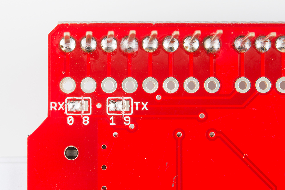
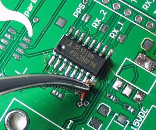
Rerouting and Green Wire Repair
Lets take a look at Nate's tutorial about Wireless Arduino Programming with Electric Imp. While modifying the serial UART connection with a hobby knife, an adjacent trace was accidentally cut!
Don’t see the problem? Here's a close up of the severed connection.
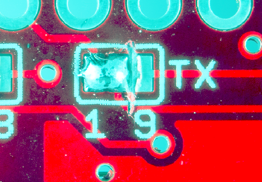
Unfortunately, Nate was going too fast and TX trace to the Imp ended up accidentally cut. After troubleshooting and probing the connection using a multimeter, he discovered the TX was not connected.
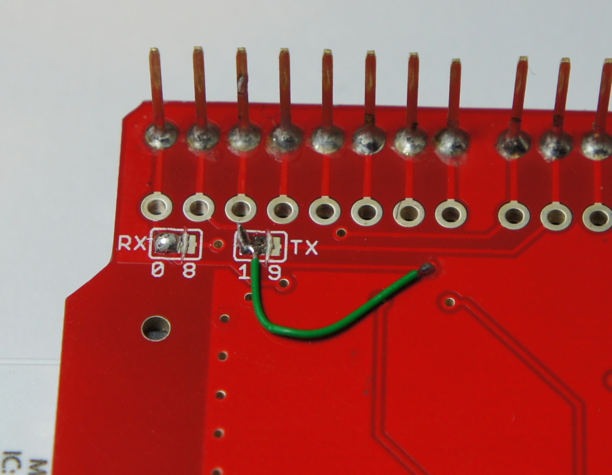
With some wire, wire strippers, and some locking tweezers, the trace was quickly repaired by connecting to the tented via. The board was recovered and started working as expected once the connection was repaired.
Remember to take extra time and care when cutting traces so as to not cut beyond or nick nearby traces!
Resources and Going Further
Now that you know how to modify jumper pads, cut traces, and reroute connections, it’s time to get out there and make some projects!
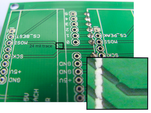
Check below for more information about recovering PCB boards from manufacturing errors or accidentally damaged pads.
 |
 |
| Recovering a board from a PCB Manufacturing Error. | "Green" Wire Repairs with a bad PCB design or damaged pad. |
Need some inspiration? Check out these jumper pad designs implemented on these SparkFun boards:
- Binary Blaster
- Simon Says PTH Kit
- Simon Tilts
- GPS Logger Shield
- Electric Imp 2-pin jumper
- ESP8266 Thing Development Board
If you decide to design your own jumper pads, try looking at the Eagle packages for jumper pads which can be found on GitHub in SparkFun's Eagle Library: