Electric Imp Breakout Hookup Guide
 jimblom,
  Shawn Hymel
impRoduction
The Electric Imp is a deviously awesome development platform. Disguised as an every day SD card, the imp is actually a unique combination of microprocessor and WiFi module. The imp makes connecting any device to the Internet a breeze. Looking to catch on with this "Internet of Things" fad? The imp is an excellent place to start.
In this tutorial, we'll be explaining how to use the imp card with one of our Breakout Boards as well as the imp002 breakout board. You will have the choice of which platform to use (the imp card or the imp002).
First, we'll cover how to hook up the hardware end of the imp and imp002. Following that we'll head over into the firmware domain, programming the imp to blink LEDs and read analog and digital inputs. The last code example shows off the coolest part of the imp: controlling hardware over the Internet!
Required Materials
You have a choice to make! You can either use the imp card and Breakout Board, or you can use the imp002 Breakout Board.
If you want to use the imp card, you will need an imp card and the Electric Imp Breakout Board.

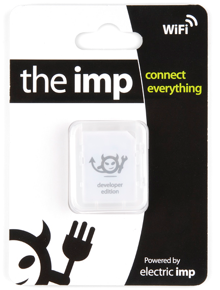
Electric Imp
WRL-11395
SparkFun Electric Imp Breakout
BOB-12886If, on the other hand, you want to use the imp002, you will need the Electric Imp imp002 Breakout Board.
SparkFun Electric Imp imp002 Breakout
BOB-12958Aside from one of those platforms, we'll use a few common electronics parts you may already have. Here's a wishlist of everything else we'll be using.
In addition to those items, you'll also need the following non-SparkFun materials:
- Wireless network with Internet access
- Electric Imp planner account (sign up is free/easy)
- Electric Imp planner website pulled up in your web browser
- SmartPhone w/ the Electric Imp app (Android or iOS)
Tools
There will be some soldering involved. The Breakout Board does not come with header pins soldered on, which you'll need in order to interface with the imp's I/O pins. You'll need a simple soldering iron and a bit of solder (If you've never soldered before, this is a great place to start! The solder points are easy, through-hole jobs).
Before We Begin
This tutorial builds upon some basic electronics concepts. If you aren't familiar with any of the topics below, consider reading through that tutorial first:
- How to Solder - Through-hole
- How to Power a Project
- Voltage Dividers
- Pulse Width Modulation
- Light-emitting Diodes
Aside from the imp's programming language, Squirrel, there will be a variety of coding languages used in later parts of this tutorial -- primarily HTML and Javascript. Don't worry if you're not too familiar with those, as the examples aim to be short, sweet, and easy-to-modify.
Let's start by overviewing the imp hardware itself. It's hard, at first, to wrap your head around the fact that this little, module is actually a powerful WiFi-enabled microcontroller platform.
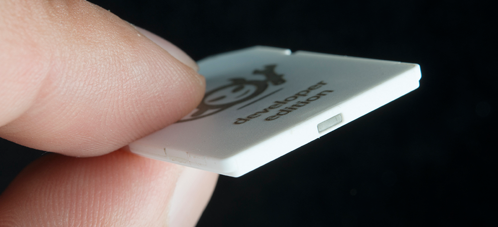
About the imp Card
It may look like an everyday SD card, but the imp is much, much more. It's a WiFi-enabled microprocessor. It's programmable over the air. It's got GPIOs, UARTS, I2C and SPI interfaces, pulse-width-modulation, digital-to-analog and analog-to-digital converters. Basically, it's what you'd get if you smushed an ARM microprocessor and a WiFi module down into a tiny SD-card-sized package.
The imp provides an easy, integrated way to connect almost any hardware device to Internet services. It is well suited to be the backbone of your Internet-enabled project, whether you're remotely controlling your electric blanket or triggering an irrigation system via a web browser. Connecting your imp to a wireless network and programming it is a simple, streamlined process.
The Hardware: 6 Wondrous I/Os
The imp is basically made of pure awesome. But, if we lift the hood of awesomeness for a moment, we can talk a bit about the imp's hardware. The platform of the imp is a Cortex-M3 microprocessor. Just like any microprocessor, the imp has a collection of input and output pins, each with unique functions. There are six addressable I/O pins -- not as many as an Arduino, but it makes up for it in terms of functionality. The imp has three UARTs, two I2C and SPI interfaces, and two DAC outputs; plus each pin can act as an ADC input and PWM output.
| Pin # | UART1289 | UART57 | UART12 | I2C89 | I2C12 | SPI257 | SPI189 | DAC | ADC | PWM |
|---|---|---|---|---|---|---|---|---|---|---|
| 1 | CTS | TX | SCL | SCLK | Yes | Yes | Yes | |||
| 2 | RTS | RX | SDA | MISO | Yes | Yes | ||||
| 5 | TX | SCLK | Yes | Yes | Yes | |||||
| 7 | RX | MOSI | Yes | Yes | ||||||
| 8 | TX | SCL | MOSI | Yes | Yes | |||||
| 9 | RX | SDA | MISO | Yes | Yes |
Of course, each of those pins can also be used as a simple inputs (with or without pull-up resistors) or outputs, sinking/sourcing up to 4mA each.
Also in that tiny SD package is a WiFi module, an antenna, and a light sensor. We'll find out why the light sensor is critical in the coming pages.
The imp is a 1.8-3.3V device, supplying it any more voltage than that can be harmful. It can require up to 400mA (worst-case), but it'll usually pull about 80mA (even 5mA in a power-save mode).
The IDE
All code written for the imp is done online, in a browser-based integrated development environment (IDE). Everyone can (freely) create their own account on the IDE, where both your programs and your imps are kept safe and secure. There are certainly pros and cons to this “always online” approach (though you can write and save every program locally, and upload it when you’re ready). Still, it seems like a good solution for this type of platform.
Code in the IDE is divided into two halves: the imp device, and the agent. Code in the device half is code that actually runs on your imp. The agent is a process living on Electric Imp's cloud server. It can communicate with both your imp, and the outside Internet world. We'll dig further into the differences between these two components later.
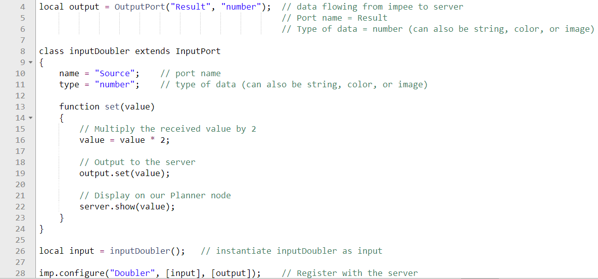
The Language: Squirrel
Firmware for the imp is written in a language called Squirrel. Squirrel is an object oriented language similar to Javascript, but unlike most embedded system programming languages we've encountered (namely Arduino). Entering imp development from the world of Arduino may be somewhat jarring. There are no loop() or setup() functions, instead most actions are event or timer-driven.
There are tons of great examples on Electric Imp's wiki page, and if you're truly interested in learning Squirrel, check out the Squirrel homepage. There's also the Electric Imp API to familiarize yourself with. These are functions and libraries used to perform actions with the imp's GPIO pins and other hardware functionality.
About the Breakout
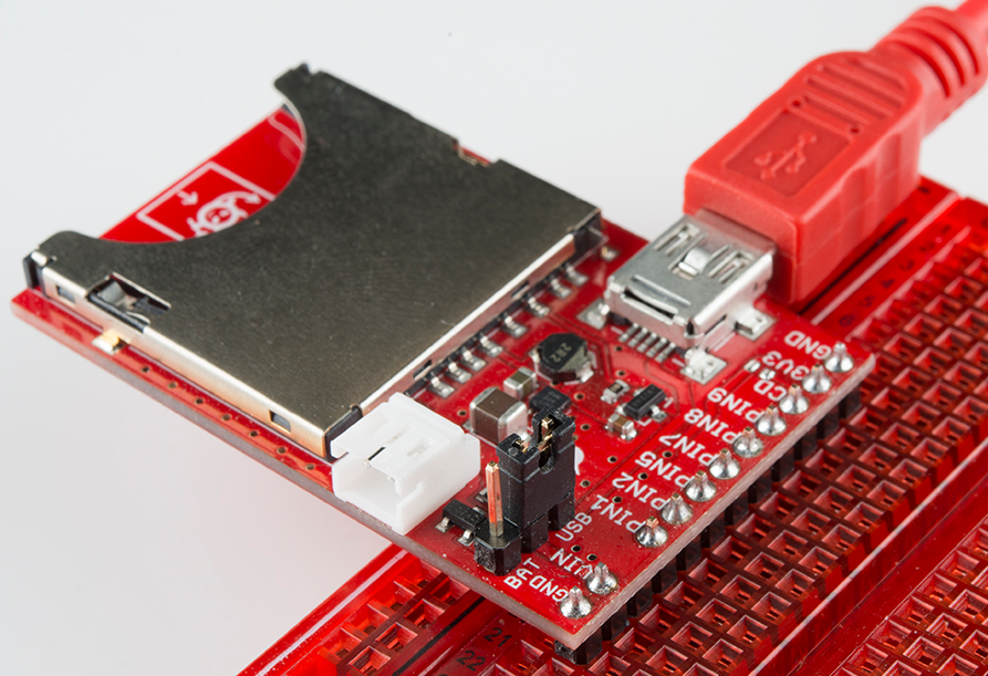
In order to use an imp, two pieces of hardware are required: the imp card and the impee. An impee is the piece of hardware that houses the imp. Aside from having a standard SD socket for the imp to slide into, the impee also needs to provide power to the imp, and do something with the imp's I/O pins. Our impee for this tutorial is as simple as it gets...a breakout board.
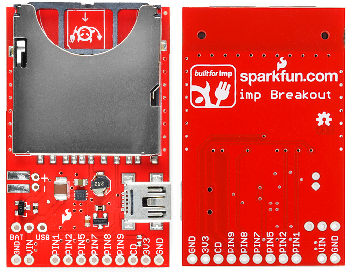
The imp breakout provides the bare minimum you should need to add an imp to your project. There's an SD socket, a step-down voltage regulator, and every I/O pin of the imp is broken out to a 0.1"-spaced header.
Powering the Breakout
A big chunk of the circuitry on the Breakout board is a 3.3V TPS62172 step-down regulator (and the inductor/capacitors supporting it). This regulator allows for input voltages anywhere between 3.3V and 17V (voltages in the upper end of that range may produce some heat). It can support up to 500mA of continuous current.
There are three power inputs on the board, all of which, are fed into the on-board 3.3V regulator:
- "VIN" header - This standard 0.1" header feeds directly into the 3.3V regulator.
- Battery input - These are the pins and pads labeled "+" and "-". The footprint of the two through-hole pins matches up to a PTH 2-pin JST connector, which mates with our LiPo batteries (or AA batteries). This input needs to be selected using the jumper (see below).
- USB mini-B connector - This power input should feed a clean, 5V source into the breakout board's regulator. The USB voltage supply can come from either a mini-B cable connected to your computer or a USB wall adapter. This input needs to be selected using the jumper (see below).
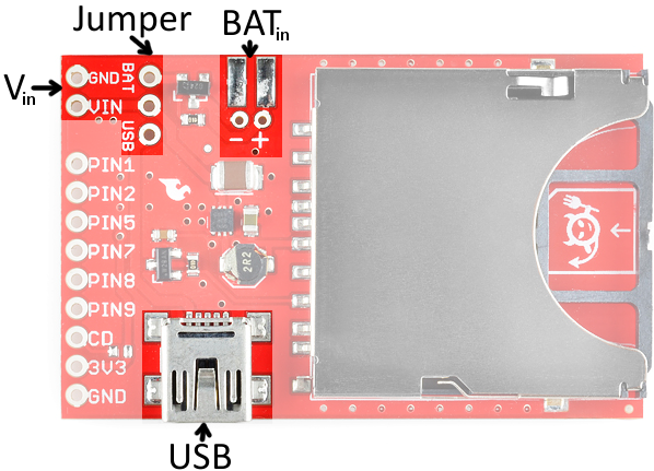
Setting the Jumper
To use either the battery or USB power inputs, a jumper must be set on the board. To use the jumper, first solder a 3-pin male header to the jumper pins. Then use a 2-pin jumper to span from the middle pin, to whichever of the two inputs you'd like to use.
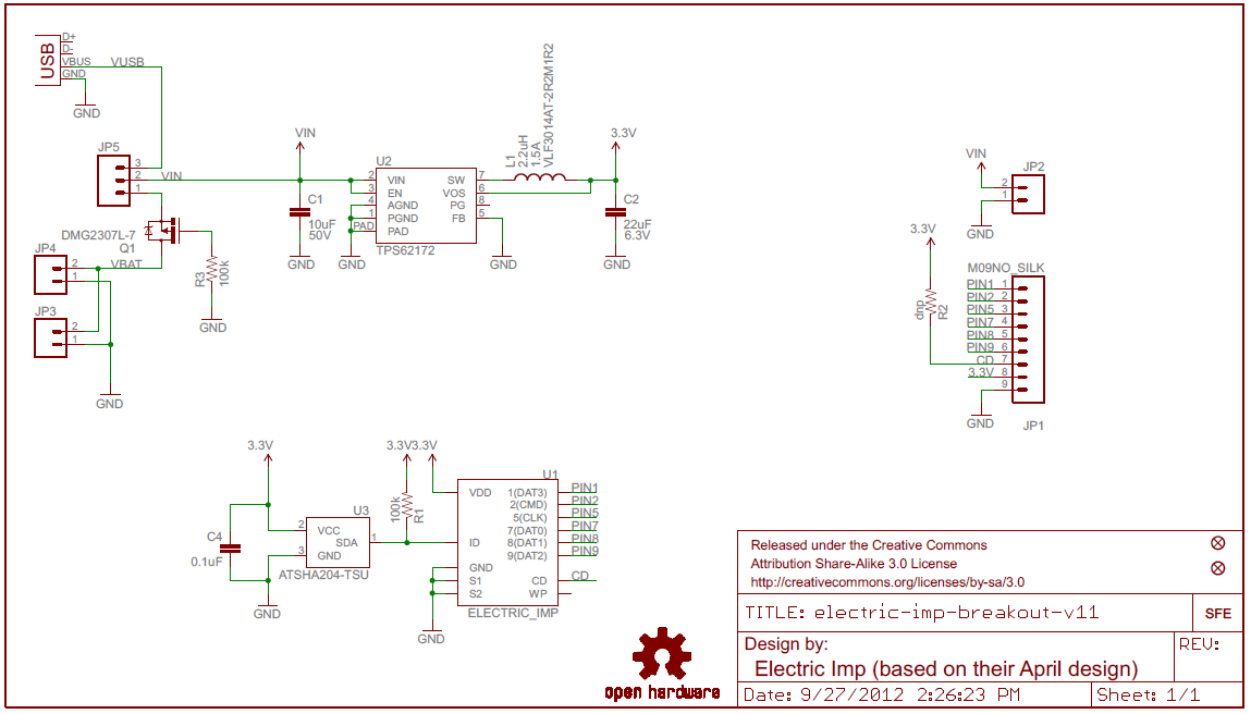
The Breakout's Schematic
There are three main components to the breakout board: a TPS62172 step-down regulator (U2), the Electric Imp socket (U1), and the ATSHA204 authentication chip (U3).
Pinout
All of the imp's GPIO pins are broken out to the 0.1"-spaced header, along with a few related power pins:
- GND - Common pin for input voltage
- VIN - Input voltage supply fed into regulator
- PIN1 - imp pin 1 (UART1289 CTS, UART12 TX, I2C12 SCL, SPI189 SCLK, DAC, ADC, PWM)
- PIN2 - imp pin 2 (UART1289 RTS, UART12 RX, I2C12 SDA, SPI257 MISO, ADC, PWM)
- PIN5 - imp pin 5 (UART57 TX, SPI257 SCLK, DAC, ADC, PWM)
- PIN7 - imp pin 7 (UART57 RX, SPI257 MOSI, ADC, PWM)
- PIN8 - imp pin 8 (UART1289 TX, I2C89 SCL, SPI189 MOSI, ADC, PWM)
- PIN9 - imp pin 9 (UART1289 RX, I2C89 SDA, SPI189 MISO, ADC, PWM)
- CD - Card detect. This signal will connect to GND whenever a card is inserted into the socket.
- 3V3 - 3.3V output from regulator
- GND - Common ground
ID Chip
There's actually one more piece of hardware required of the impee: an ID chip, which provides each impee with a unique identification code. This means that every impee you encounter should include an Atmel ATSHA204 authentication chip. The imp automatically interfaces with this chip every time it boots up, so it can identify which impee it's plugged into. This actually turns out to be pretty awesome, because the program that an imp runs depends on what impee it's plugged into. If you had two impees in your house -- say controlling an irrigation system and another controlling a coffee machine -- one, single imp would run two different programs depending on which machine it was plugged into.
You shouldn't ever have to fuss with the ID chip. In fact, you can forget we ever said anything about the ATSHA204!
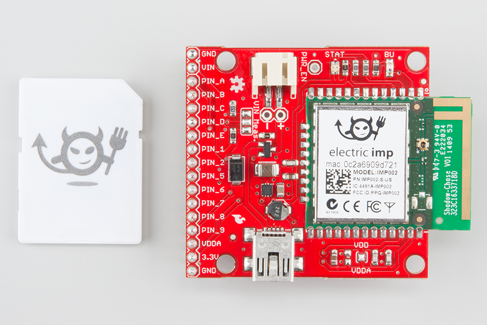
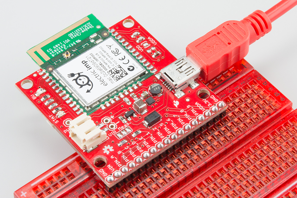
About the imp002 Breakout
The imp002 is a solder-down module version of the original imp card. We have done the hard work of creating a breakout board for you. Now, you just need one board instead of 2 to get started with the electric imp!

We recommend you read the About the imp section to learn what is in the imp, what the Planner is, and a brief overview of the Squirrel language. Like the imp card, the imp002 module contains an embedded ARM Cortex-M3 microprocessor, an onboard WiFi module, and antenna.
The Hardware: 12 Glorious I/Os
We have broken out 12 I/O pins from the imp002 module to standard 0.1" headers. Much like the imp card, these pins can be used for a variety of functions.
| Pin # | UART1289 | UART57 | UART12 | UART6E | UARTB | I2C89 | I2C12 | SPI257 | SPI189 | DAC | ADC | PWM |
|---|---|---|---|---|---|---|---|---|---|---|---|---|
| A | Yes | |||||||||||
| B | RX | Yes | ||||||||||
| C | Yes | |||||||||||
| D | ||||||||||||
| E | RX | |||||||||||
| 1 | CTS | TX | SCL | SCLK | Yes | Yes | Yes | |||||
| 2 | RTS | RX | SDA | MISO | Yes | Yes | ||||||
| 5 | TX | SCLK | Yes | Yes | Yes | |||||||
| 6 | TX | |||||||||||
| 7 | RX | MOSI | Yes | Yes | ||||||||
| 8 | TX | SCL | MOSI | Yes | Yes | |||||||
| 9 | RX | SDA | MISO | Yes | Yes |
Powering the imp002 Breakout
The imp002 Breakout Board contains a 3.3V TPS62172 step-down regulator (and the inductor/capacitors supporting it). This regulator allows for input voltages anywhere between 3.3V and 17V (voltages in the upper end of that range may produce some heat). It can support up to 500mA of continuous current.
There are three power inputs on the board, all of which, are fed into the on-board 3.3V regulator:
- "VIN" header - This standard 0.1" header feeds directly into the 3.3V regulator.
- Battery input - These are the pins labeled "+" and "-" as well as the JST connector, which mates with our LiPo batteries (or AA batteries).
- USB mini-B connector - This power input should feed a clean, 5V source into the breakout board's regulator. The USB voltage supply can come from either a mini-B cable connected to your computer or a USB wall adapter.
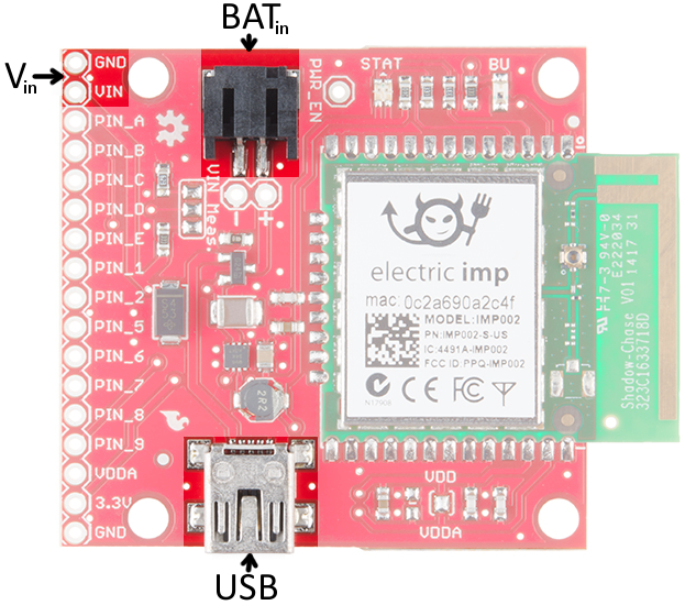
NOTE: There is a voltage selector circuit on the imp002 Breakout Board that will automatically use whichever voltage is higher: battery or USB. Be aware that the circuit does NOT charge the battery, it just prevents current flowing back into the source with the lower voltage (i.e. a short).
The imp002 Breakout's Schematic
There are a number of circuits used to support the imp002, all of which can be found on the imp002 Breakout Board.
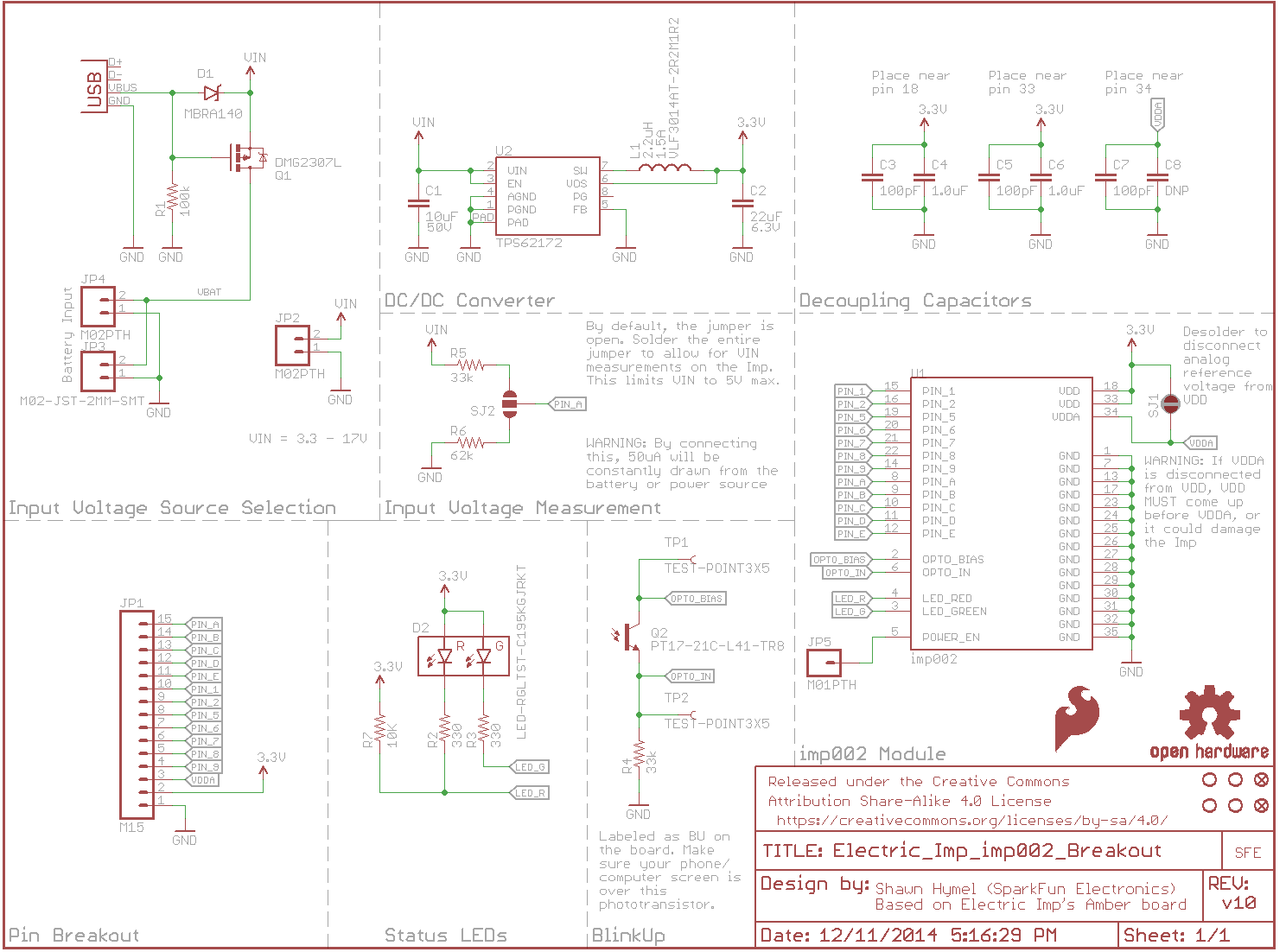
- Input Voltage Source Selection - automatically switches between USB and battery input (whichever voltage is higher)
- Pin Breakout - Power and I/O pins from the imp002 module
- DC/DC converter - the TPS62172 buck regulator and supporting components
- Input Voltage Measurement - the jumper can be soldered to allow VIN measurements on PIN A
- imp002 module - the imp module and decoupling capacitors
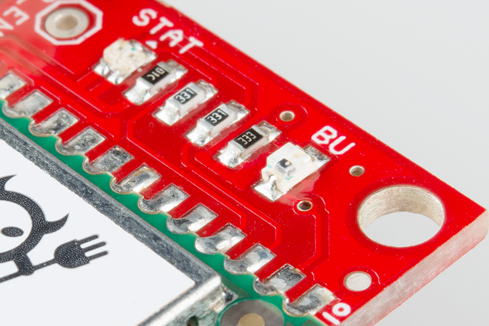
- Status LED - the red/green LED required by the imp to display its status (connecting, error, etc.)
- BlinkUp - Light sensor for sending WiFi credentials to the imp002 module
Pinout
All of the imp's GPIO pins are broken out to the 0.1"-spaced header, along with a few related power pins:
- GND - Common ground
- VIN - Input voltage supply fed into regulator
- PIN_A - imp002 pin A (ADC)
- PIN_B - imp002 pin B (UARTB RX, ADC)
- PIN_C - imp002 pin C (PWM)
- PIN_D - imp002 pin D
- PIN_E - imp002 pin E (UART6E RX)
- PIN_1 - imp002 pin 1 (DAC, UART1289 CTS, UART12 TX, I2C12 SCL, SPI189 SCLK, DAC, ADC, PWM)
- PIN_2 - imp002 pin 2 (UART1289 RTS, UART12 RX, I2C12 SDA, SPI257 MISO, ADC, PWM)
- PIN_5 - imp002 pin 5 (UART57 TX, SPI257 SCLK, DAC, ADC, PWM)
- PIN_6 - imp002 pin 6 (UART6E TX)
- PIN_7 - imp002 pin 7 (UART57 RX, SPI257 MOSI, ADC, PWM)
- PIN_8 - imp002 pin 8 (UART1289 TX, I2C89 SCL, SPI189 MOSI, ADC, PWM)
- PIN_9 - imp002 pin 9 (UART1289 RX, I2C89 SDA, SPI189 MISO, ADC, PWM)
- VDDA - ADC reference voltage. Connected to 3.3V by default.
- 3.3V - 3.3V output from regulator
- GND - Common ground
Hardware Hookup
The hardware hookup approach in this guide is just one of many ways to use the board. The breakout is made to be a versatile extension of the imp. You can connect whatever you want to the imp pins, and power the board however your project requires.
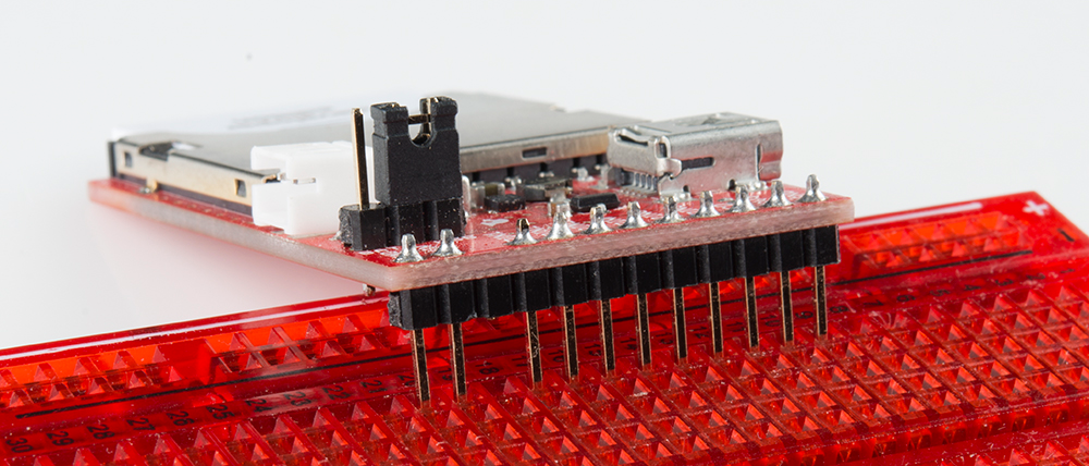
Solder Headers
In order to do much with the input/output capability of the imp, you'll need to solder to the broken out pins. If you want to use the imp Breakout with a breadboard or perfboard, 0.1" male headers make for a good choice. Depending on your application, you could swap the headers with wire, female headers, screw terminals, or a variety of other connectors.
We're going to solder male headers into the board, so we can use it with a breadboard later on.

Apply Power
Depending on what you want to use for your power source there are a few options here. You could use the on-board USB connector. Or you could solder down a 2-pin JST connector, and plug battery (LiPo or AA) into the board to make it mobile. If you go with either of those options on the imp card Breakout, you'll also need to set the jumper (the imp002 Breakout will automatically select the higher voltage).
Alternatively, you can apply power straight to the headers labeled "VIN" and "GND". This pin bypasses the jumper and goes straight to the regulator.
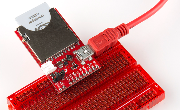
Plug in the imp!
If you have the original imp card, plug the imp card in so the suspicious little imp logo is facing up. If you've got power to the board, once plugged in, the imp should start blinking orange. If there's no blinking on the card, it's probably not getting any power. Double-check that the jumper is set correctly.
If you have the imp002, the status LED should start blinking orange as soon as you apply power.
What's all that blinking signify? How do we get the imp connected to our wireless network? Read on!
BlinkUp
Blink Codes
The imp has an internal red/green LED, which is used to tell the world what state it's currently in. If you've just plugged the imp in, and haven't told it how to get on your WiFi network, it should be blinking orange (red/green simultaneously). Here are the rest of the codes to look out for:
| Color | Speed | imp State |
|---|---|---|
| Orange | 1 Hz | No WiFi settings |
| Green | Single Pulse | Successfully received configuration via Blinkup. |
| Red | Triple-pulse | Failed to receive configuration via Blinkup. |
| Red | 1 Hz | Attempting to connect to WiFi. |
| Red, Orange, Off | 1 Hz | Getting IP address (via DHCP). |
| Orange, Red, Off | 1 Hz | Got IP address, connecting to server. |
| Green | 0.5 Hz | Connected to cloud (turns off after 60 seconds). |
| Red | 2 Hz | Connection lost, attempting to reconnect. |
| None | Normal operation |
Let's make that LED blink green! Time to send a BlinkUp.
BlinkUp
To get your imp connected to your WiFi network as well as the online imp servers, you need to go through the process Electric Imp calls commissioning. There's a great write-up on the commissioning process over on Electric Imp's Getting Started page. Here's the gist of it, as well as a few tips.
Before you begin, you'll need to make an Electric Imp account by visiting the IDE page.
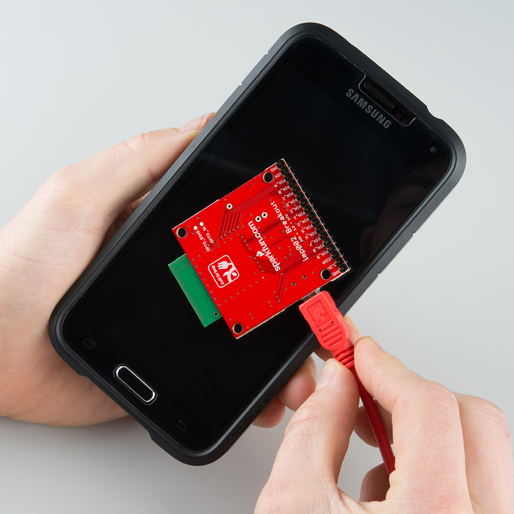
Updating the imp with your WiFi credentials is a unique process. The imp card has a built-in light sensor, looking out of the little window on the short, flat edge of the imp. The imp002 has an external light sensor built into the breakout board. The light-sensor can be used to process small amounts of precisely modulated data in the form of a blinking light.
To generate this blinking light, you need the Electric Imp app installed on your smartphone (iOS or android). Go download that app if you haven't already!
Follow the directions in the app, and prepare to update the imp with your WiFi network. Then, when your settings all look correct, hit the Send BlinkUp button. Quickly place the screen of the phone as close to the imp's light sensor as possible.
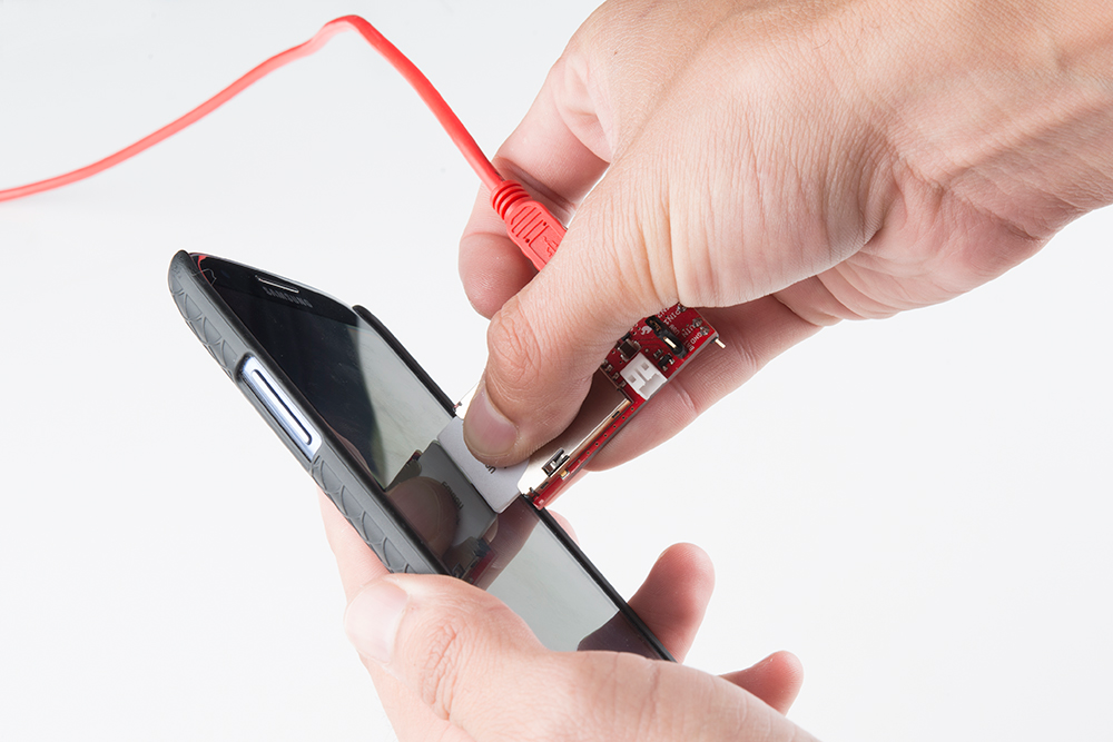
If all goes well, there should be a very short green blip of the LED, followed by a few blinks of red and orange. When the imp starts blinking green once a second, you know you've got your imp commissioned yay!
Troubleshooting
If you're imp isn't yet in the blinky green phase, use the LED blink codes to find out where it's failing. Here are some recommended steps, depending on the failure point:
- Connecting to the server (orange, red, off) - Make sure there's no firewall blocking the imp's way to the Internet (and make sure your WiFi network has an Internet connection in the first place).
- Getting IP address via DHCP (red, orange, off) - Double check your WiFi password.
- Attempting WiFI connection (red) - Double check your WiFi network name (SSID).
If all of the above are set correctly, try sending the BlinkUp one more time. We've found that it helps to close out all other app, or even try resetting your phone if it continues to fail.
More troubleshooting information can be found on Electric Imp's site.
Example 0: Hello World
Now that your imp is commissioned, it's time to upload your first bit of code!
As with any new development platform, our first goal is to make sure we can make an LED blink. If you can make an LED blink, you're well on your way to spinning motors or communicating with sensors.
Using the IDE
To begin, go to Electric Imp IDE, and log in if you haven't already.
If your Electric Imp was successfully commissioned, you should see your imp device appear under Unassigned Devices on the left-hand side.
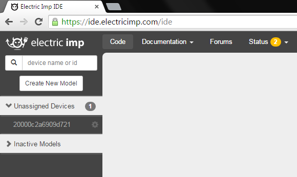
Click the Create New Model button.
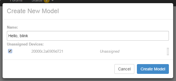
In the name field, type "Hello, blink" for the name of our model. Check the box next to our device under Unassigned Devices. Click Create Model.
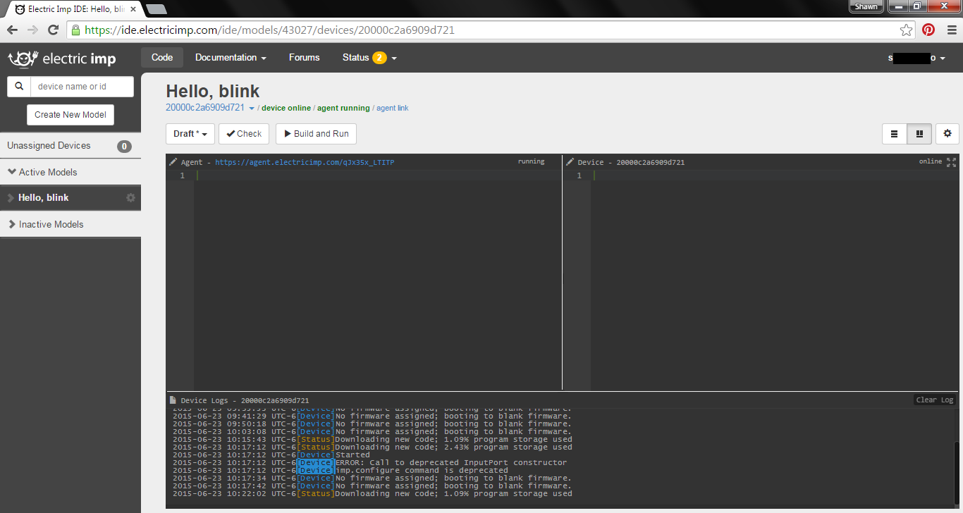
Now, on the left side, you should see a new tab called Hello, blink. Select than, then click your imp name. This is the standard view of the imp IDE. It's split into three sections:
- Agent -- This is code that runs external to your imp, in the cloud. You can offload server tasks, like HTTP requests, here. There are built in functions to aid in communication between imp and agent.
- Device -- This is the code that your imp runs. This is where you do all of your hardware control, like writing pins high and low, or reading inputs.
- Log -- This is where messages and errors are printed (using the
server.log()function).
Now we're ready to load some code and blink some LEDs!
The Circuit
The circuit for this example is very simple. We only need to connect an LED to pin 1. Don't forget your current-limiting resistor (330 Ω)!
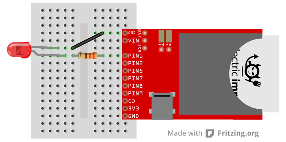
Any of the imp's I/O pins would work for this example. After working with the code, see if you can modify it to blink on other pins (or all of them!).
Hello, blink Code
We'll only be working with the Device portion of the IDE right now. Copy and paste the code below into the middle section of your window.
language:squirrel
/* Hello, Blink
   by: Jim Lindblom
   SparkFun Electronics
   date: October 31, 2013
   license: Beerware. Use, reuse, and modify this code however you see fit.
   If you find it useful, buy me a beer some day!

   This is an Electric Imp hello, world blink sketch. It'll blink an LED
   connected to pin 1, once every second.
*/

////////////////////////////////////////
// Global Variables                   //
////////////////////////////////////////
ledState <- 0;

////////////////////////////////////////
// Function definitions               //
////////////////////////////////////////

// Loop constantly updates the LED. If ledState is 1, we'll turn the LED on and
// set ledState to 0. Vice-versa is ledState is 0 coming in. This function
// schedules a wakeup in 1 second, and calls itself again.
function loop()
{
    if (ledState)
    {
        hardware.pin1.write(1); // Write pin 1 high
        ledState = 0; // Flip ledState
    }
    else
    {
        hardware.pin1.write(0); // Write pin 1 low
        ledState = 1; // Flip ledState
    }

    // This must be called at the end. This'll call loop() again in 1s, that way
    // it'll actually loop!
    imp.wakeup(1.00, loop);
}

////////////////////////////////////////
// Setup Stuff: Runs first at startup //
////////////////////////////////////////
hardware.pin1.configure(DIGITAL_OUT);   // Configure Pin 1 as digital output

loop(); // Call loop, and let the program go!
Then hit the >Build and Run button up top, and enjoy the blinks.
Shortcut heads up! If you're a neurotic CTRL+S saver, the standard save shortcut does save, but it also attempts to build and run your code. If successful, it'll upload the code and immediately start running on your imp. If there's an error, you'll start hearing about it in the log window.
Into the Code
If you’re only used to working with Arduino sketches, this code may make very little sense, Electric Imp programs have a very different “flow” to them. Begin by looking at the 2 lines of code at the bottom (under the “Setup Stuff” header). This is actually where our imp starts when it begins to run it’s program. Everything above is simply a function or variable definition.
The majority of this code deals with the imp’s pin class, which handles all of the I/O control. If you’re used to using Arduino GPIO’s, the imp’s API isn’t too different. You have to set the pin up as either an input or output, analog or digital. Then write or read to the pin accordingly.
At the end of the setup, we make a call to a loop() function, which is defined above. loop() is simple, it checks a global variable named ledState. If ledState is 1 we turn the LED on, if it's 0 we turn the LED off.
To write a pin high or low, we call the hardware.pin1.write([0:1]) function. You can probably extrapolate from that how to control the other five pins.
The special sauce making loop actually loop is the last line of code in the function: imp.wakeup(1.00, loop). The imp.wakeup function puts the imp to sleep, but sets a timer. When the timer goes off, the requested function (loop in this case) function is called from its beginning. In this case we set the timer to 1.00 seconds, so loop() should run once a second. This is really the only way to make the imp “loop” like an Arduino might.
Check out the comments in the code for a more in-depth overview of each function call. Or, for more information, check out Electric Imp’s API reference.
Example 1: I/O Control
The imp can do most anything an Arduino or similar microcontroller can. It's got analog-to-digital converters, PWM, SPI, I2C, UARTs, and it even has digital-to-analog converters. In this snippet of example code, we'll dig further into the imp's I/O control delving into digital and analog input/output.
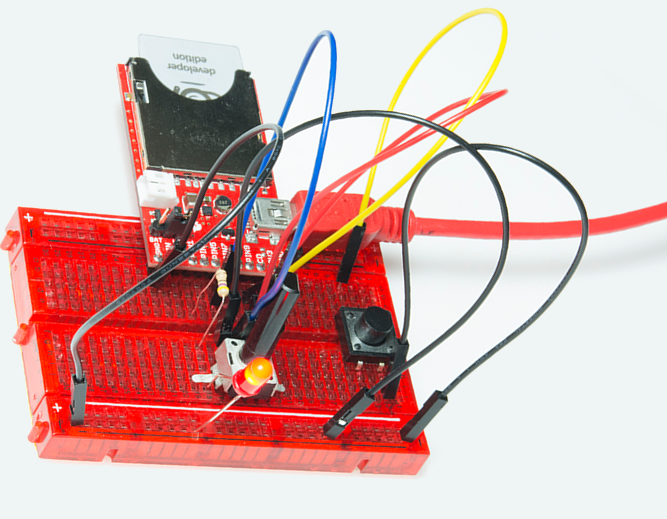
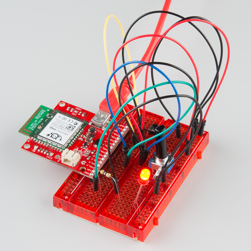
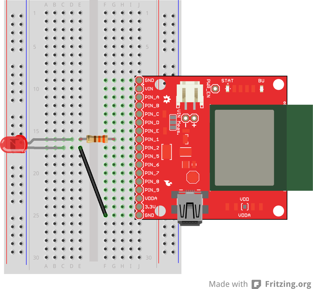
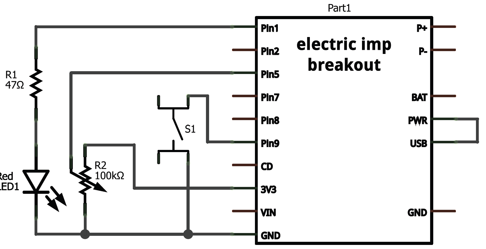
The Circuit
The setup for this example code requires three unique components: an LED, potentiometer, and a button (plus a current-limiting resistor for the LED). Here's a fritzing diagram and schematic (click to see it bigger) for our circuit:
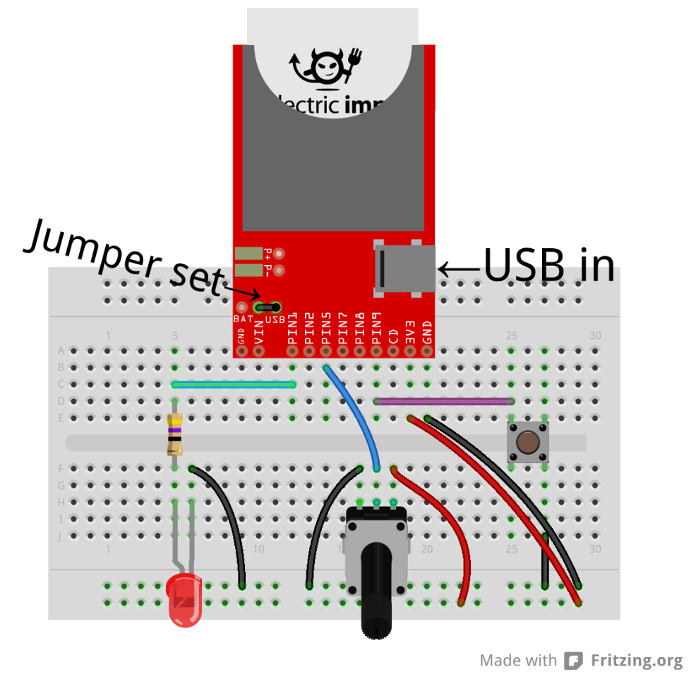
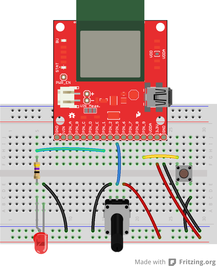
Make sure the imp is getting power. USB is usually the quickest/easiest way to apply power to the breakout board, but you'll need to set the jumper accordingly on the breakout.
The IDE
To create a new piece of code, we need to create a new "model" and associate it with our Breakout Board impee. To do this, hover over your impee and click the "settings" gear. The familiar Device settings window should pop up. Under the _Associated model: box, create a new model named I/O Control. Then click Save Changes.
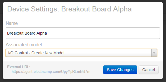
This will create a new tab on the left side labeled I/O Control. If you expand that tab, you'll see that the Breakout Board impee has be reassigned there.
The Code
Once again, we'll only be using the Device portion of the IDE. Copy and paste everything from the below box, into your Device window and click Build and Run up top.
language:Squirrel
/* Digital Input, Analog Input, PWM Output Example
   by: Jim Lindblom
   SparkFun Electronics
   date: July 15, 2013
   license: Beerware. Use, reuse, and modify this code however you see fit.
   If you find it useful, buy me a beer some day!

   This is a simple piece of code which uses an LED, potentiometer, and button.
   The LED connects to pin 1 through a 47 ohm resistor. The cathode of the LED should connect to ground.
        This means writing pin 1 will turn the LED on, and writing it to 0 turns the LED off.
   The button connects on one side to pin 9, and the other pin of the button goes to ground.
        We'll use the internal pull-up resistors on pin 9 to bias the button high.
        When the button is pressed, pin 9 should read as low.
   The wiper of the potentiometer is connected to pin 5. The other two pins of the pot should be
        connected to +3.3V and GND. This'll make the voltage at pin 5 adjustable from 0-3.3V.
*/

////////////////////////////////////////
// Function definitions               //
////////////////////////////////////////

local ledState = 1; // Says local, but think of this as a global var. Start with LED on

// function pin9Changed() will be called whenever pin 9 goes from high->low or low->high
function pin9changed()
{
    local buttonState = hardware.pin9.read(); // Read from the button pin

    if (buttonState == 0) // Button will read low if pressed
    {
        ledState = ledState ? 0 : 1;    // Flip flop ledState
        server.log("Button pressed!");
    }
    else // Otherwise button was released, no action
    {
        server.log("Button released");
    }
}

// Loop constantly updates the LED. If ledState is 1, we'll read the pot, and set the LED brightness accordingly.
// If ledState is 0, we'll just turn the LED off. ledState is updated in the pin9Changed() function.
function loop()
{
    if (ledState == 1)
    {
        local rawValue = hardware.pin5.read();  // Read from the potentiometer. Returns a value between 0 and 65535.
        rawValue /= 65535.0;  // Make rawValue a % (and a float). The pin write function requires a value between 0 and 1.
        hardware.pin1.write(rawValue);  // Pin 1 is already configured as PWM, write potentiometer value
    }
    else
    {
        hardware.pin1.write(0);  // Write pin 1 low -- LED off
    }

    // This must be called at the end. This'll call loop() again in 10ms, that way it'll actually loop!
    imp.wakeup(0.01, loop);
}

////////////////////////////////////////
// Setup Stuff: Runs first at startup //
////////////////////////////////////////
hardware.pin1.configure(PWM_OUT, 0.0005, 0.0);   // Configure Pin 1 as PWM output, 5ms period, 0% high (off)
hardware.pin5.configure(ANALOG_IN); // Configure pin 5 as analog input
hardware.pin9.configure(DIGITAL_IN_PULLUP, pin9changed); // Configure pin 9 as digital input (with pull-up enabled). On change it'll call function pin9changed().
imp.configure("LED Trigger Wiper", [], []);

loop(); // Call loop, and let the program go!
The code creates an adjustable-brightness LED controller. The brightness of the LED is adjusted by turning the potentiometer. Pressing the button will turn the LED on and off.
Explaining the Code
The skeleton of this code acts a lot like that of Hello, blink. The function definitions are up top, the setup stuff runs at the bottom, and loop() is called at the beginning. loop() continually calls itself, using the imp.wakeup(0.01, loop) function call, every 10 ms.
The loop() function again relies on an ledState variable. If ledState is 1, we read the potentiometer voltage, and adjust the brightness of our LED accordingly.
The ledState variable is flip-flopped in the pin9changed() function. This is like an interrupt. It's called whenever the state of pin 9 changes -- if it goes from high to low, or low to high. When setting up pin 9 as a digital input, we added this function as the one to be called when the state change occurred.
Check out the comments in the code for a more in-depth overview of each function call. Or, for more information, check out Electric Imp's API reference.
Enough hardware stuff! The next two examples will make use of the imp's greatest feature...it's web connectivity.
Example 2: Web Control (Request)
Some of the most fun you can have with the imp is connecting it to the Internet, and interfacing it with web pages. In this example, we’ll use a simple HTML/Javascript web page to control some LEDs connected to the imp.
This time, we'll not only be writing code for the imp, but the agent as well. This example code will show how to pass data from the imp to the agent, and how to write a simple web page to interact with the agent half of the code.
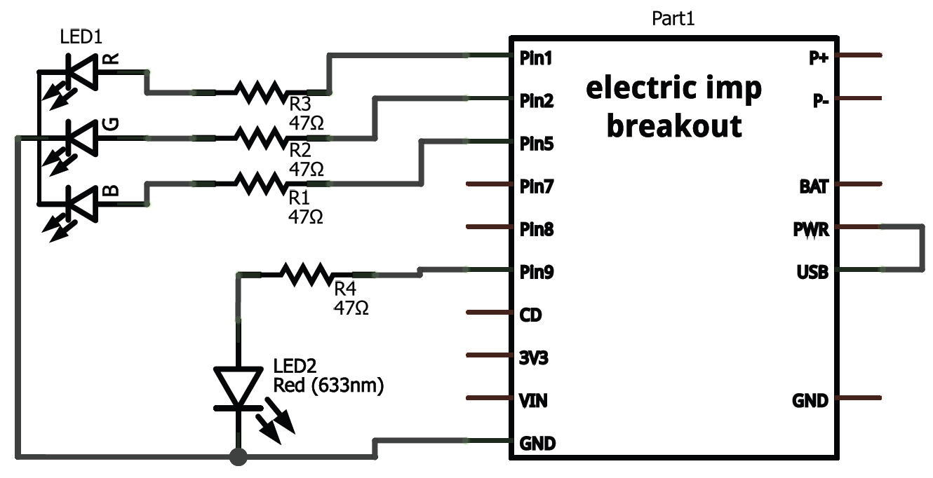
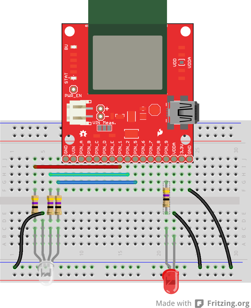
The Circuit
The circuit for this example is very simple: a common-cathode RGB LED is connected to the imp's pins 1, 2, and 5 (red, green, and blue anodes respectively), and another basic red LED is connected to pin 9 of the imp. Don't forget to add some current limiting resistors (in the range of 50-100Ω)!
The imp (Device) Code
Create a new model, as you did in the last example. We'll call this one LED Web Control. Copy and paste the code below into the Device section of the IDE.
language:javascript
/* Electric Imp Web-controlled LEDs
    by: Jim Lindblom
    SparkFun Electronics
    date: November 1, 2013
    license: Beerware. Please use, reuse, and modify this code.
    If you find it useful, buy me a beer some day!

    This is a simple Electric Imp example, which shows how to interface
    the imp with an agent and webpage. This example code goes hand-in-hand with
    an HTML webpage. Check out this page for more information:
    https://learn.sparkfun.com/tutorials/electric-imp-breakout-hookup-guide/example-2-web-control
    This will show how you can use html color, text, and radio form inputs
    to control LEDs on/off, PWM them, and set a timer to turn them off.

    Circuit:
    A common cathode RGB LED is connected to the imp's pins 1, 2, and 5.
    The red anode connects to 1 through a 47 Ohm resistor, green 2, and blue 5.
    The cathode of the LED connects to ground.
    Another simple, red LED is connected to the imp to imp pin 9, through
    another 47 Ohm resistor. The cathode of the LED is grounded.
*/

imp.configure("LED Web Control", [], []); // Configure the imp

///////////////
// Pin Setup //
///////////////
// Setup reference variables for our pins:
redPin <- hardware.pin1;   // R of RGB
greenPin <- hardware.pin2; // G of RGB
bluePin <- hardware.pin5;  // B of RGB
ledPin <- hardware.pin9;   // Lonely red LED

// Configure our pins:
ledPin.configure(DIGITAL_OUT);        // Simple digital output
redPin.configure(PWM_OUT, 0.01, 0);   // PWM output 10ms clock, off
greenPin.configure(PWM_OUT, 0.01, 0); // PWM output 10ms clock, off
bluePin.configure(PWM_OUT, 0.01, 0);  // PWM output 10ms clock, off

/////////////////////////////////
// Agent Function Declarations //
/////////////////////////////////
// setLed will turn the lonely red LED on or off.
// This function will be called by the agent.
function setLed(ledState)
{
    ledPin.write(ledState);
}

// setRGB will take a table input, and set the RGB LED accordingly.
// the table input should have parameters 'r', 'g', and 'b'.
// This function will be called by the agent.
function setRGB(rgbValue)
{
    bluePin.write(rgbValue.b/255.0);
    redPin.write(rgbValue.r/255.0);
    greenPin.write(rgbValue.g/255.0);
}

// setUser will print out to the log the name of the LED changer
// This function will be called by the agent.
function setUser(suspect)
{
    server.log(suspect + " set the LEDs.");
}

// setTimer will turn the LEDs off after a specified number of seconds
// This function will be called by the agent.
function setTimer(time)
{
    if (time != 0)
        imp.wakeup(time, ledsOff); // Call ledsOff in 'time' seconds.
}

///////////////////////////////////
// Important Agent Handler Stuff //
///////////////////////////////////
// Each object that the agent can send us needs a handler, which we define with
// the agent.on function.  The first parameter in agent.on is an identifier
// string which must be matched by the sending agent. The second parameter is
// the name of a function to be called. These functions are already defined up
// above.
agent.on("led", setLed);
agent.on("rgb", setRGB);
agent.on("user", setUser);
agent.on("timer", setTimer);

//////////////////////
// Helper Functions //
//////////////////////

// ledsOff just turns all LEDs off.
function ledsOff()
{
    ledPin.write(0);
    redPin.write(0);
    greenPin.write(0);
    bluePin.write(0);
}
The key bit of new code in this example is the agent.on function call. Run during the setup portion of the code, these function calls set up a handler function to be called whenever the agent sends a specific string to the imp. For example, the agent.on("led", setLed); functions says that whenever a message tagged with an "led" string is received from the agent, call the setLed() function.
How do we send messages from the agent to the imp? Looks like it's time to start using the other half of the IDE window...
The Agent Code
The agent is a piece of squirrel code living and running in the Electric Imp cloud. While the imp is managing all of its hardware pins, the agent can be off mingling with other servers and dealing with Internet traffic. There are built in functions which allow the imp to send data to the agent, and vice-versa.
In this example, we'll set the agent up to listen for HTTP requests. Upon receiving a request, the agent will parse the query, and relay the important information back to the imp.
Copy and paste this code into the Agent half of your LED Web Control model:
language:javascript
/* Agent for imp Web-Controlled LEDs
    by: Jim Lindblom
    SparkFun Electronics
    date: November 1, 2013
    license: Beerware. Please use, reuse, and modify this code.
    If you find it useful, buy me a beer some day!

    This is the agent portion of the LED Web Controller. It defines how http
    requests to https://agent.electricimp.com/XXXXXXXXXXXX are handled. Check
    your agent URL to find out what, exactly, XXXXXXXXXXXX is.

    For example, if your agent url is https://agent.electricimp.com/UpyYpRLmBB7m
    sending https://agent.electricimp.com/UpyYpRLmBB7m?led=0 should turn the
    lonely red led off.  https://agent.electricimp.com/UpyYpRLmBB7m?led=1 would
    turn the LED on.

    * There are also request handlers for "rgb", which should be a #RRGGBB
      formatted string. E.g: https://agent.electricimp.com/UpyYpRLmBB7m?rgb=%238500b7
    * A "user" request handler can receive a string. E.g.: https://agent.electricimp.com/UpyYpRLmBB7m?user=Jim
    * And a "timer" handler looks for a number-looking string. E.g.:
      https://agent.electricimp.com/UpyYpRLmBB7m?timer=10

    The parameters can be combined in one request. E.g.:
    https://agent.electricimp.com/UpyYpRLmBB7m?led=1&rgb=%237f3fff&timer=10&user=Jim
*/

// At the start, print a message to say we're online, and print the agent URL:
server.log("LED Web Control Agent Online: " + http.agenturl());

// requestHandler handles all http requests coming into the agent. It's only
// setup to look for a select few requests: "led", "rgb", "user" and "timer".
function requestHandler(request, response)  {

    try { // Try provides us with exception handling, in case a runtime error occurs

        // check if the user sent led as a query parameter
        if ("led" in request.query) {
            // if they did, and led=1.. set our variable to 1
            if ((request.query.led == "1") || (request.query.led == "0"))
            {
                // convert the led query parameter to an integer
                local ledStatus = request.query.led.tointeger();

                // send "led" message to device, and send ledState as the data
                device.send("led", ledStatus);
            }
        }
        // check if an "rgb" query was received:
        if ("rgb" in request.query) {
            // colors are sent as a string, we've got to do some work to convert
            // them to a number, which is eventually what we'll need to do
            // pwm on our RGB led pins.
            local color = request.query.rgb; // get the query into a variable
            if (color[0] == '#') { // The request should start with '#' (%23)
                // We'll construct a table with three parameters: r, g, and b
                // Do some work to convert r, g, and b from ASCII characters
                // to 0-255 values.
                local returnTable = {
                    r = ASCIItoHex(color[1])*16 + ASCIItoHex(color[2])
                    g = ASCIItoHex(color[3])*16 + ASCIItoHex(color[4])
                    b = ASCIItoHex(color[5])*16 + ASCIItoHex(color[6])
                };
                device.send("rgb", returnTable); // send our color table to the imp
            }
        }
        // check if a "user" query was received.
        if ("user" in request.query) {
            device.send("user", request.query.user); // Simply pass the value out to the imp.
        }
        // check if a "timer" query was received:
        if ("timer" in request.query) {
            // convert to an integer, and pass it out to the imp.
            device.send("timer", request.query.timer.tointeger());
        }
        // send a response back saying everything was OK.
        response.send(200, "OK");
    }
    catch (ex) {
        response.send(500, "Internal Server Error: " + ex);
    }
}

// Set up a handler for HTTP requests. This is the function that we defined above.
// https://electricimp.com/docs/api/http/onrequest/
http.onrequest(requestHandler);

//////////////////////
// Helper Functions //
/////////////////////////////

// This function converts an ASCII character to a number
function ASCIItoHex(colorNibble) {
    if ((colorNibble >= '0') && (colorNibble <= '9')) {
        return colorNibble - 48;
    }
    else if ((colorNibble >= 'a') && (colorNibble <= 'f')) {
        return colorNibble - 87;
    }
    else if ((colorNibble >= 'A') && (colorNibble <= 'F')) {
        return colorNibble - 55;
    }
}
Check out the comments in the code for a line-by-line dissection. Most of the code on the agent is an HTTP request handler (the requestHandler(request, response) function). This function uses a series of if statements to check for a specific request parameter key (like "led" or "rgb"). In those if statements, the agent decides what to do with the parameter value (if anything) and sends a message to the imp using the device.send function.
With both of those halves of code added to your model, and the circuit built, build and run the model. Time to test it out!
Testing the Model
After initially running the model, you shouldn't see anything happen to your imp or the LEDs it's connected to. To change that, we need to send an HTTP request to the agent.
First, we need to locate the URL of our agent, which is printed at the top of your Agent window. It'll be something like https://agent.electricimp.com/0123456789ABCDEF. Each imp gets its own, unique, agent URL.
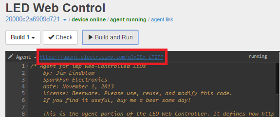
We can send requests to the agent by adding URL query strings onto the agent URL. For example, type https://agent.electricimp.com/qJx35x_LTITP?led=1 (make sure you replace my unique code with your own!) into your browser's address bar and go. Notice anything happen on your imp circuit? The lonely red LED should have turned on! Look through the agent code to see what other parameters we can send.
We can even add multiple parameters to the same request, for example try going to https://agent.electricimp.com/qJx35x_LTITP?led=1&rgb=%234080ff&timer=10 in your browser. This request turns on the LED, but it also sends an RGB string to control the RGB LED and it sets a timer to turn all LEDs off.
This is very cool, but typing these parameters into an address bar is a pain! Let's write a simple HTML webpage to take a form input and do all of that for us!
The HTML Code
This is the last piece to the puzzle -- a simple HTML page that takes a form input, and sends that information out to our Electric Imp agent.
Create a local file on your computer called impControl.html. Open it with a text editor, and paste the below code into it.:
<html>
<head>
</head>

<body onLoad=updateURL()>

<h4>What is your agent's url?</h4>
<form name="url">
https://agent.electricimp.com/<input type="text" name="agentUrl" placeholder="qJx35x_LTITP" onChange=updateURL()>
</form>

<h4>Imp Inputs:</h4>
<form name="leds" id="ledSend" method="get">
Lonely Red LED: <input type="radio" name="led" value="0" checked>Off
                <input type="radio" name="led" value="1">On<br>
Set the RGB LED: <input type="color" name="rgb">  (Chrome/Opera use color input, other browsers format as "#XXXXXX", where X is 0-9, a-f, or A-F.) <br>
How long should the LEDs stay on? <input type="text" name="timer" value="10">seconds<br>
Your name? So we know who to blame! <input type="text" name="user" placeholder="Your name here"><br>
<br>
<input type="submit" value="Update!">
</form>

</body>

<script language="javascript">

 function updateURL() {
    ledForm = document.leds;
    urlForm = document.url;
    ledForm.action = "https://agent.electricimp.com/" + urlForm.agentUrl.value;
}

</script>

</html>
Then save and open the file with your browser of choice. A simple web page like this should show up:
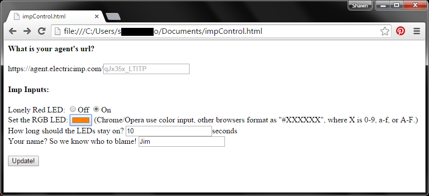
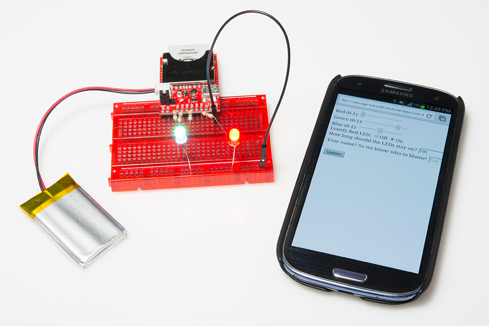
Make sure you type in the correct, unique code for your agent URL. Then play with the rest of the form inputs. The On/Off radio buttons turn the lonely red LED on or off. The RGB color selector sets the color of the RGB LED. The duration text box will turn all LEDs off after a set number of seconds. And the name textbox will print your name in your imp’s console. Try it out!

The code should be pretty easy to pattern-match and modify. The agent checks for specific values (like "led" or "rgb"), which are set by the name identifiers in the HTML form. To add, subtract, or modify those, simply add/remove/modify the form inputs, and add an if statement to look for it in the agent.
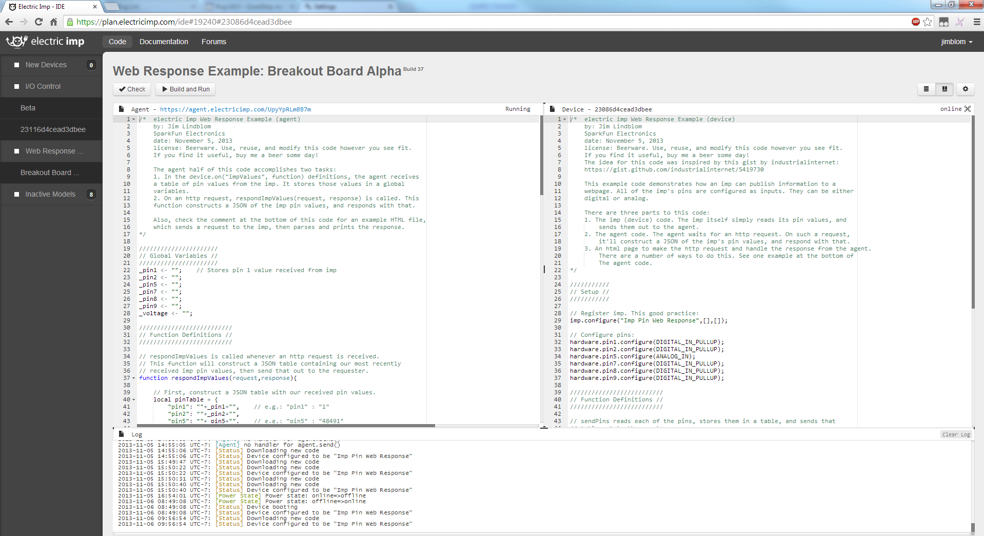
Example 3: Web Response
In the previous example, we used a web page to send data to the imp. But what if you wanted to send data from the imp back to a web page? This example shows how to use the imp to post a response to a web server. Maybe you want to monitor the light level in your garage with a simple photocell? Or live stream the temperature in your backyard. This is the example you'll want to start with.
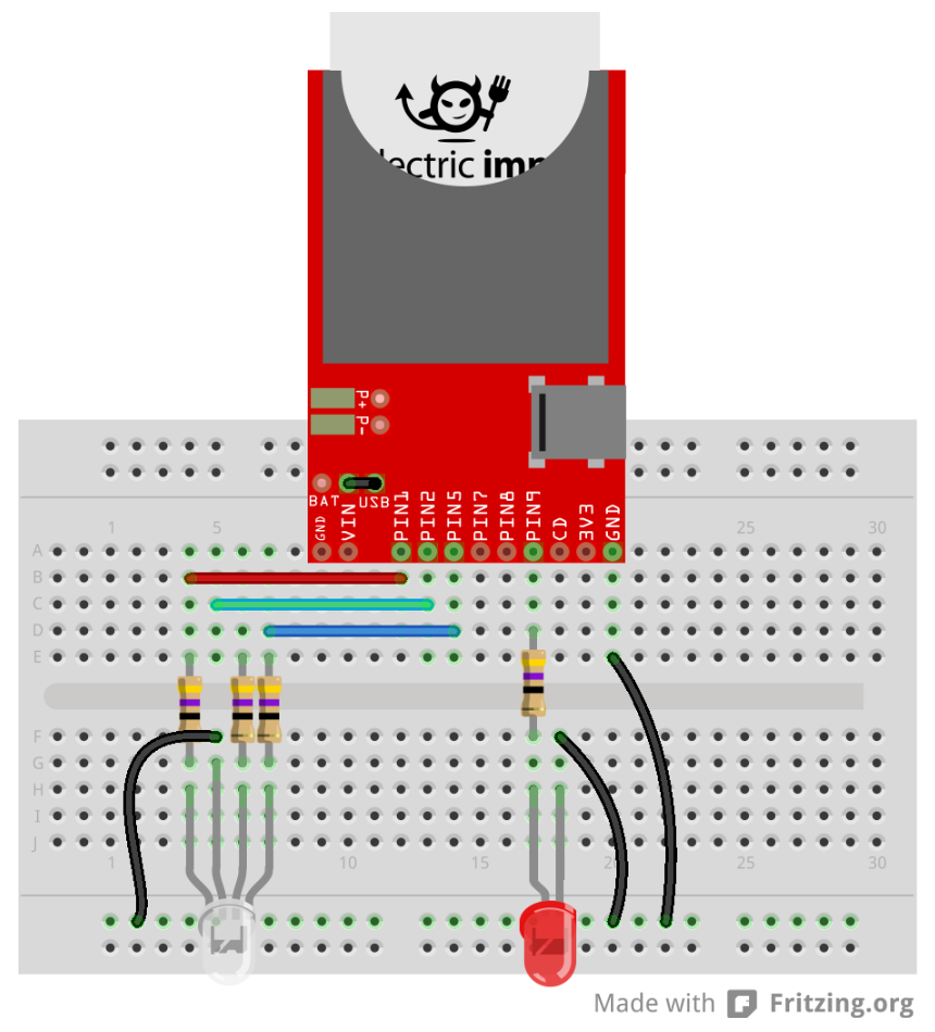
The Circuit
The circuit for this example is very open-ended. If you have any digital or analog components you'd like the imp to read, hook them up to one of it's inputs. For example, if you want to monitor a button-press and a photocell, hook up a circuit like this:
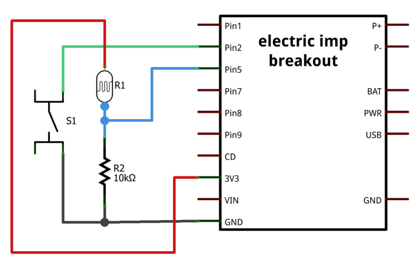

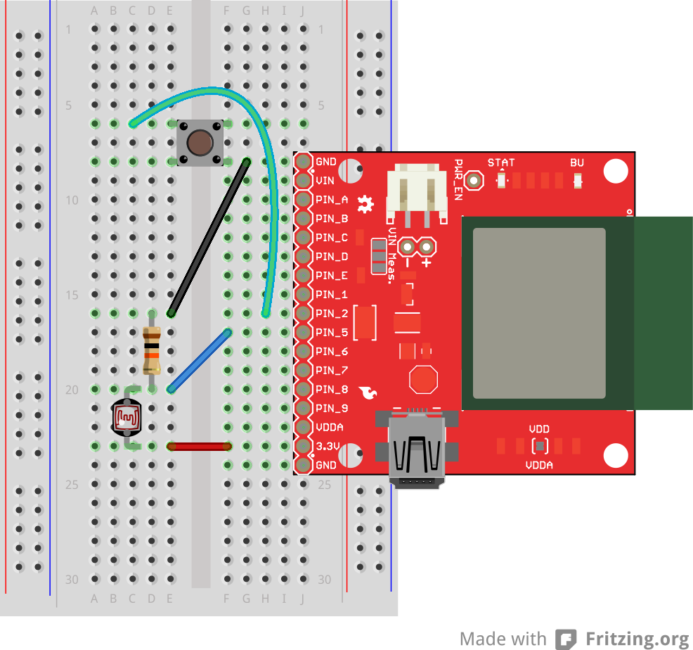
Feel free to make the circuit your own. Maybe add a tilt sensor or an analog temperature sensor to one of the unused pins. At this point you should feel somewhat comfortable modifying the imp's pin functions to make them do what you want.
The Imp Code
Once again, we'll need a few pieces of code to make everything work together. Move your impee into a new model and name it Web Response Example.
Starting with the imp again, copy and paste this code into the Device section of your IDE:
language:javascript
/*  Electric Imp Web Response Example (device)
    by: Jim Lindblom
    SparkFun Electronics
    date: November 5, 2013
    license: Beerware. Use, reuse, and modify this code however you see fit.
    If you find it useful, buy me a beer some day!
    The idea for this code was inspired by this gist by industrialinternet:
    https://gist.github.com/industrialinternet/5419730

    This example code demonstrates how an imp can publish information to a
    webpage. All of the imp's pins are configured as inputs. They can be either
    digital or analog.

    There are three parts to this code:
    1. The imp (device) code. The imp itself simply reads its pin values, and
        sends them out to the agent.
    2. The agent code. The agent waits for an http request. On such a request,
        it'll construct a JSON of the imp's pin values, and respond with that.
    3. An html page to make the http request and handle the response from the agent.
        There are a number of ways to do this. See one example at the bottom of
        The agent code.
*/

///////////
// Setup //
///////////

// Register imp. This good practice:
imp.configure("Imp Pin Web Response",[],[]);

// Configure pins:
hardware.pin1.configure(DIGITAL_IN_PULLUP);
hardware.pin2.configure(DIGITAL_IN_PULLUP);
hardware.pin5.configure(ANALOG_IN);
hardware.pin7.configure(DIGITAL_IN_PULLUP);
hardware.pin8.configure(DIGITAL_IN_PULLUP);
hardware.pin9.configure(DIGITAL_IN_PULLUP);

//////////////////////////
// Function Definitions //
//////////////////////////

// sendPins reads each of the pins, stores them in a table, and sends that
// table out to the agent.
// It calls itself every 100ms -- 10 times a second.
function sendPins()
{
    // Read each of the pins and store them in a table.
    // The key names -- "pin1", "pin2", etc. -- should be kept the same, unless
    // you also change them in the device.on() function on the agent.
    local pinValues =
    {
        pin1 = hardware.pin1.read(),
        pin2 = hardware.pin2.read(),
        pin5 = hardware.pin5.read(),
        pin7 = hardware.pin7.read(),
        pin8 = hardware.pin8.read(),
        pin9 = hardware.pin9.read(),
        voltage = hardware.voltage()    // We'll also send the operating voltage.
    }

    // Once the table is constructed, send it out to the agent with "impValues"
    // as the identifier.
    agent.send("impValues", pinValues);

    // Schedule a wakeup in 100ms, with a callback to this function.
    imp.wakeup(0.1, sendPins);
}

sendPins(); // Call sendPins once, and let it do the rest of the work.
Per usual, check out the code comments for a line-by-line overview of what's going on. The new function this time? agent.send(string, object). agent.send is used to send data from the imp, to the agent. This time we need to create a handler on the agent side to deal with the data sent by the imp.
Speaking of agent code...
The Agent Code
On the agent side we need to accomplish two tasks:
- Define an imp handler function to deal with the data sent by the imp. We'll just store the data sent by the imp into a global variable.
- Create another handler to be called when an HTTP request is received. Upon receiving the request the agent will construct a response based on the data received from the imp, and send that out to the requester.
There's the overview, here's the code. Copy and paste this into the Agent half of your model:
language:javascript
/*  Electric Imp Web Response Example (agent)
    by: Jim Lindblom
    SparkFun Electronics
    date: November 5, 2013
    license: Beerware. Use, reuse, and modify this code however you see fit.
    If you find it useful, buy me a beer some day!

    The agent half of this code accomplishes two tasks:
    1. In the device.on("impValues", function) definitions, the agent receives
    a table of pin values from the imp. It stores those values in a global
    variables.
    2. On an http request, respondImpValues(request, response) is called. This
    function constructs a JSON of the imp pin values, and responds with that.

    Also, check the comment at the bottom of this code for an example HTML file,
    which sends a request to the imp, then parses and prints the response.
*/

//////////////////////
// Global Variables //
//////////////////////
_pin1 <- "";    // Stores pin 1 value received from imp
_pin2 <- "";
_pin5 <- "";
_pin7 <- "";
_pin8 <- "";
_pin9 <- "";
_voltage <- "";

//////////////////////////
// Function Definitions //
//////////////////////////

// respondImpValues is called whenever an http request is received.
// This function will construct a JSON table containing our most recently
// received imp pin values, then send that out to the requester.
function respondImpValues(request,response){

    // First, construct a JSON table with our received pin values.
    local pinTable = {
        "pin1": ""+_pin1+"",    // e.g.: "pin1" : "1"
        "pin2": ""+_pin2+"",
        "pin5": ""+_pin5+"",    // e.g.: "pin5" : "48491"
        "pin7": ""+_pin7+"",
        "pin8": ""+_pin8+"",
        "pin9": ""+_pin9+"",
        "voltage": ""+_voltage+"" + " V",   // e.g.: "voltage" : "3.274 V"
    }

    // the http.jsonencode(object) function takes a squirrel variable and returns a
    // standardized JSON string. - https://electricimp.com/docs/api/http/jsonencode/
    local jvars = http.jsonencode(pinTable);

    // Attach a header to our response.
    // "Access-Control-Allow-Origin: *" allows cross-origin resource sharing
    // https://electricimp.com/docs/api/httpresponse/header/
    response.header("Access-Control-Allow-Origin", "*");

    // Send out our response.
    // 200 is the "OK" http status code
    // jvars is our response string. The JSON table we constructed earlier.
    // https://electricimp.com/docs/api/httpresponse/send/
    response.send(200,jvars);
}

// device.on("impValues") will be called whenever an "impValues" request is sent
// from the device side. This simple function simply fills up our global variables
// with the equivalent vars received from the imp.
device.on("impValues", function(iv) {
    _pin1 = iv.pin1;
    _pin2 = iv.pin2;
    _pin5 = iv.pin5;
    _pin7 = iv.pin7;
    _pin8 = iv.pin8;
    _pin9 = iv.pin9;
    _voltage = iv.voltage;
    });

///////////
// Setup //
///////////

// http.onrequest(function) sets up a function handler to call when an http
// request is received. Whenever we receive an http request call respondImpValues
// https://electricimp.com/docs/api/http/onrequest/
http.onrequest(respondImpValues);
There are two things to point out here. The first is the device.on function. This function sets up a handler to be called when the imp sends a defined string. In this case, we're looking for the imp sending "impValues". The data associated with this string is a table, full of all of the imp's pin readings. That function is called every time the imp sends that specific string to the agent.
The real magic happens in the respondImpValues() function. The agent sets this function as the handler for any HTTP request (using the http.onrequest function). This function constructs a JSON string of data, in the form of ""key":"value", "key":"value", ...,", which the requesting HTTP client should be able to parse and understand.
Check the comments in the code for more information on the agent code.
For now, Build and Run the code. Don't expect it to do anything of interest until we add the last bit of magic...
The Web App -- AJAX, jQuery, JSON Oh My!
The final piece to this puzzle is constructing a web page that can both send an HTTP request and deal with the response from the agent.
Create a new HTML file named pinView.html. Paste the code below into it.
<html>
<head>
    <title>Electric Imp Breakout</title>
    <script src="http://code.jquery.com/jquery-1.9.1.min.js"></script>
    <script src="http://code.jquery.com/mobile/1.3.1/jquery.mobile-1.3.1.min.js"></script>
    <script>
        $( function() {
            // Edit these values first! The externalURL variable should be the
            // unique URL of your agent. e.g. the last part of:
            // https://agent.electricimp.com/UpyYpRLmBB7m
            // pollRate defines how often the values on your page will refresh.
            var externalURL ="UpyYpRLmBB7m";
            var pollRate ="1000";

            function poll(){
                // Construct an ajax() GET request.
                // http://www.w3schools.com/jquery/ajax_ajax.asp

                $.ajax({
                    type: "get",
                    url: "https://agent.electricimp.com/"+externalURL,  // URL of our imp agent.
                    dataType: "json",   // Expect JSON-formatted response from agent.
                    success: function(agentMsg) {   // Function to run when request succeeds.

                        // jQuery find "pin1" id and overwrite its data with "pin1" key value in agentMsg
                        $("#pin1").html(agentMsg.pin1);
                        $("#pin2").html(agentMsg.pin2);
                        $("#pin5").html(agentMsg.pin5);
                        $("#pin7").html(agentMsg.pin7);
                        $("#pin8").html(agentMsg.pin8);
                        $("#pin9").html(agentMsg.pin9);
                        $("#vin").html(agentMsg.voltage);

                        updateBG(agentMsg.pin5);    // Try this if you have a photocell connected to pin 5
                    },
                    error: function(err) {
                        console.log("err"+ err.status)
                    }
                });
            }

            // setInterval is Javascript method to call a function at a specified interval.
            // http://www.w3schools.com/jsref/met_win_setinterval.asp
            setInterval(function(){ poll(); }, pollRate);

            // This function updates the
            function updateBG(lightSensor)
            {
                if (lightSensor > 30000)
                {
                    document.body.style.backgroundColor = "#FFFFFF";
                }
                else
                {
                    document.body.style.backgroundColor = "#AAAAAA";
                }
            }
        });
    </script>
</head>
    <body>
        <h3>Imp Pins:</h3>
        <div id="pins">
        <p> <b>Pin 1:</b> <span id="pin1"><!-- This is where the pin 1 reading will go --></span></p>
        <p> <b>Pin 2:</b> <span id="pin2"><!-- This is where the pin 2 reading will go --></span></p>
        <p> <b>Pin 5:</b> <span id="pin5"><!-- This is where the pin 5 reading will go --></span></p>
        <p> <b>Pin 7:</b> <span id="pin7"><!-- This is where the pin 7 reading will go --></span></p>
        <p> <b>Pin 8:</b> <span id="pin8"><!-- This is where the pin 8 reading will go --></span></p>
        <p> <b>Pin 9:</b> <span id="pin9"><!-- This is where the pin 9 reading will go --></span></p>
        <p> <b>Voltage:</b> <span id="vin"><!-- This is where the voltage reading will go --></span></p>
    </body>
</html>
Before saving and closing the file, edit this line of code to point to your agent's unique URL:
var externalURL ="UpyYpRLmBB7m"; // Put your agent's unique URL here Sweet! Save and open the file with your favorite web browser. Assuming your imp is running with the new device/agent code, you should see something like this:
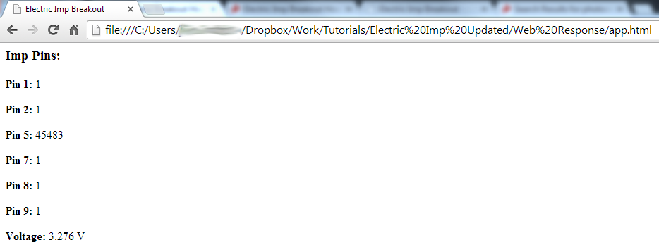
Those 1's, 0's, and other numbers might be a little different on your screen. Try pressing a button. Or cover the photocell. Or mess with the imp's pins in some other way. Are the values changing? How cool is that!
The code for this webpage is a little ugly. It uses some web "stuff" that my fragile, electrical engineer mind can barely grasp. There may be a better way to do this, but this works for us. If you find another cool way to request and use data from the imp, let us know in the discussion section!
Towards the bottom of the HTML code is a series of <span> tags, with ids like "pin1", "pin2" etc. But they're blank. Remember those, they'll come in handy.
The real magic here is happening in the poll() function in the <script> area up top. This function sets up an AJAX request to the Electric Imp agent. If the request succeeds, function(agentMsg) is executed. This function parses the JSON message received from the agent, and dynamically updates the data in our blank <span> tags defined below. poll() is set to be called every pollRate (defaulted to 1000) milliseconds.
Whew! Hopefully all of this stuff is easy enough to pattern-match and modify as you please. To make some other information stream to the webpage, you have to:
- Edit the imp Device code to send the desired data to the agent. Use the
agent.send()function to do this. - Edit the Agent code in two places:
- Read the data in from the imp in the
device.on()function. - In an HTTP request handler, send the data out as a JSON string.
- Read the data in from the imp in the
- Add something in the AJAX success function to look for the correct JSON "key" and "value" combination. Then do something with that data.
- Add a location in the HTML body to show the data. E.g.
<span id="myData"><!--Data goes here--></span>
Give it a try! It sounds like a lot of work, but most of the constructs are already there for you to quickly add new displayable data. You could print the imp's measured RSSI, or do some math on the analog input reading to turn it into a voltage.
Resources and Going Further
Now that you know how to hook up the imp and its Breakout, what project will you be making with it? Will you be adding to the "Internet of Things"? Need some inspiration? Check out some of these products and projects:
Wireless Arduino Programming with Electric Imp
Arduino Wireless Communication via the Electric Imp
If you're looking to interface an imp with an Arduino, check out the Electric Imp Shield. We've also written a tutorial on communicating via serial between the imp and Arduino.
Resources
The folks at Electric Imp have loads of great resources on their wiki. Among the many links on that page, these ones stand out for being extra helpful:
- Electric Imp API Reference - Here you'll find all of the imp-specific functions.
- Electric Imp Developer Forums - There's a wealth of knowledge in the imp community. If you've got a question, search for an answer here, or start a new topic.
- imp Card Datasheet - A good datasheet for the imp (now called the imp001). You'll find electrical characteristics here, along with other useful info.
- imp002 Datasheet - The datasheet for the imp002 module.
If you're still left with imp-related questions, try consulting their forums.