Arduino Wireless Communication via the Electric Imp
 jimblom
Introduction
Imagine two Arduinos, half-a-globe away from each other, talking and sharing sensor information over a serial port, as if they were right next to each other. When we stuck the Electric Imp on an Arduino shield, this is just the beginning of what we were envisioning.
Our goal with this tutorial is to create a black box "data pipeline" to move information from one Arduino to another, utilizing a Internet-connected WiFi networks. The Arduinos will simply share data across a serial bus, ignorant to the crazy-complicated path that data is taking to reach the other side.
Why the Imp? There are dozens of ways to connect your Arduino to the world-wide-web and share data -- WiFi Shields, WiFi XBees, Cellular Shield name a few -- but the Electric Imp is one of the cheapest and easiest solutions. Plus, it's a good excuse to learn about and toy with the awesome little development platform.
What You'll Need
We'll focus on using the Electric Imp Shield, but there are a variety of hardware setups that can be made to work. Here is an example wishlist of what you might need to use the Imp Shield and a RedBoard:
If you want to communicate from one Arduino to another, you'll need to double the quantities on each of those items, but you can test the setup with a single 'duino and Imp combo.
In place of the Shield, you could pair an Electric Imp Breakout with a breadboard, jumper wires and headers.
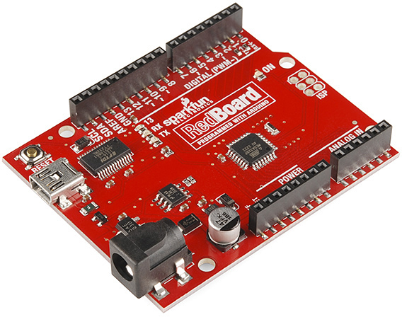
We'll use a RedBoard, but, of course, any Arduino-compatible board should work.
Suggested Reading
- Electric Imp Breakout Hookup Guide -- This tutorial serves as an introduction to the Electric Imp. We definitely recommend reading through the hookup guide before proceeding with this tutorial, it'll help you get your Imp's all set up.
- What is an Arduino? -- If you've never used Arduino before, this tutorial will introduce you to the popular beginner-friendly platform.
- Serial Communication -- There'll be a lot of talk about serial communication in this tutorial. If you're unfamiliar with baud rates, RX, or TX, definitely take some time to read through this tutorial.
The Plan
Let's quickly discuss the components involved in our Arduino-to-Arduino data pipeline, from the Imp to the Impee to the Arduino.
The Electric Imp
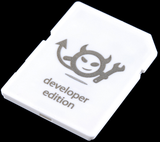
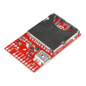
The Electric Imp is a powerful WiFi-enabled development module disguised as an SD card. It's incredibly easy to get up-and-running, and equally easy to code and use. It works perfectly as an intermediary between the hardware world and the world-wide-web.
Among the many features packed into the tiny Electric Imp module is a trio of UARTs, which handle asynchronous serial communication. Serial communication just happens to be one of the more popular Arduino-to-machine communication methods. So, the goal is to setup a serial-based portal of communication between the Imp and Arduino.
The Electric Imp Agent
Using the Electric Imp IDE, Imps can be programmed to communicate with an agent. An Electric Imp agent is a server-side piece of Squirrel code that can pass data to-and-from the Imp, and also deal with Internet traffic.
In this tutorial we'll need to write separate pieces of code for the Imp and the agent. They'll work hand-in-hand to transmit data between Arduinos.
The Impee
To use any Electric Imp, you'll need an Impee - the host board or socket that is designed to interface with the Imp. For this tutorial, our Impees are going to be the Imp Shield, but you could also make do with the Imp Breakout, or an Impee of your own design.
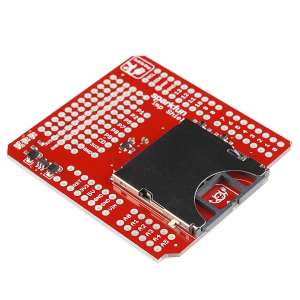
Either board will work, but the breakout will require an extra bit of wiring that the shield already takes care of. Read about that on the next page.
The Arduino.
Finally, you'll need an Arduino. Just about any Arduino should do, all you really need is a UART, which they should all have. If Arduino isn't your thing, feel free to adapt the Arduino code and hardware to your favorite microcontroller platform! We'll make use of our friend, the RedBoard.
On top of writing code for the imp and its agent, we'll also need to write a short Arduino Sketch. Just a simple example that can send data serially to the imp.
Hardware Setup
If you're using the Imp Shield, setup is as simple as soldering on some headers, plugging in the shield, and plugging the Imps in.
But if you're using a Breakout or any other form of Impee, there is a bit of hookup to be done. Here is the circuit we'll be using:
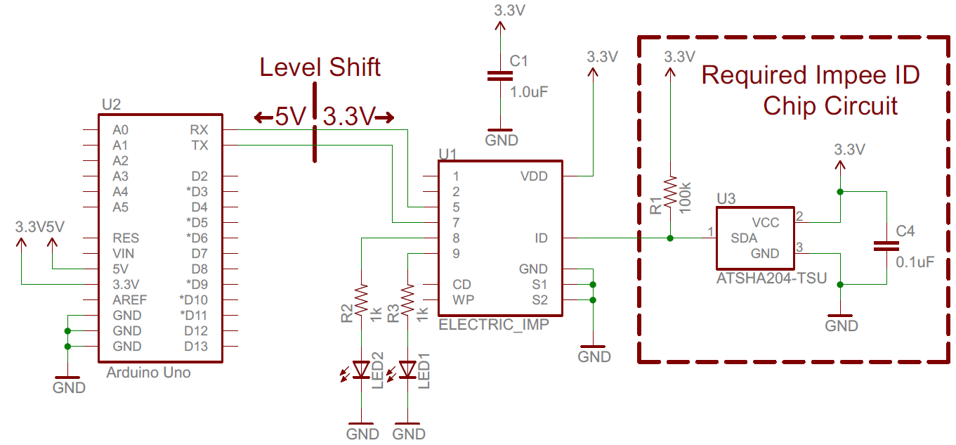
There is some wiggle room with which pins you can use. On the Imp you could use different pins to control the LEDs (or skip the LEDs entirely), or even use one of the other two UARTs (UART12 or UART1289) for communication. On the Arduino, you can use different pins for the SoftwareSerial port (double-check to make sure they'll work with the library though!).
A few things to keep in mind: the Imp is not a 5V tolerant device, so you'll need to shift down any signals above 3.3V. We recommend bi-directional level shifters to accomplish that task (that same circuit is already on the shield).
The Imp can be a power-hungry little devil -- pulling up to 400mA. We've been powering each of the Arduinos/Imp combos off purely USB, and it's worked just fine. Just make sure to keep the power requirements in mind!
We'd really encourage you to branch out on this design. The Imp's got at least 2 more pins for you to make use of. There's an I2C port available on pins 1 and 2, as well as DACs, ADCs, PWM pins...you name it. And, of course, there's tons of room left on the Arduino. Add some sensors, LCDs, LEDs...whatever your project needs!
Imp and Agent Code
The Electric Imp serves as an intermediary between the hardware world and the Internet. It can easily manage I/O pins and the UART, and it can also share data with an agent. The agent is a separate piece of server-side code, which does the higher-level "Internet-land" stuff.
Code for both the Imp and the agent is written in Squirrel, a very JavaScript-esque high-level, object-oriented programming language. For help learning Squirrel, check out these resources. For guidance more specific to the Imp, check out their Dev Center.
Before you can add code, you'll need to BlinkUp your Imp (to connect it to your WiFi), and assign your Impee. Check out the Electric Imp Hookup Guide for help there. We'll be creating a model called Serial Pipeline to house the Agent and Imp code.
The Imp Code
The code on the Imp needs to accomplish two primary tasks:
- When serial data comes in, from the Arduino, the Imp needs to pass that data up to the agent.
- When data comes down from the agent, the Imp needs to pass it through the serial port to the Arduino.
The Arduino and the agent are both, essentially, using the Imp as a pipeline to pass data.
Here is the code we came up with to accomplish that. Copy this code into the Device section of your Imp IDE:
language:c
/* Imp Serial Pipeline Device
by: Jim Lindblom
SparkFun Electronics
date: March 24, 2014
license: Beerware. Use, reuse, and modify this code however you see fit.
If you find it useful, buy me a beer some day!
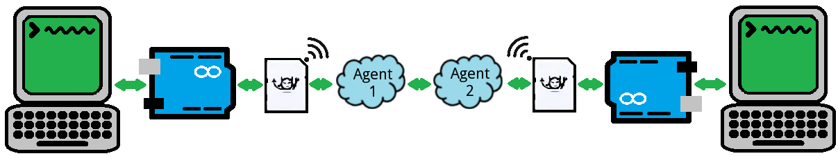
The Serial Pipeline model is designed to pass serial data from one imp to
another, anywhere across the world. Data transfers look like this:
Arduino 1 Serial Out to Imp 1 -> Imp 1 passes serial data to Agent 1 ->
Agent 1 passes data to Agent 2 -> Agent 2 passes data to Imp 2 -> Imp 2
passes data to Arduino 2 over serial. Whew.
A second Serial Pipeline model should be created to be a near exact
copy of this, except the agentURL variable (on the agent code) should be
modified to the URL of this device's agent.
The device must accomplish two tasks:
1. On serial data in, send it off to the agent. The agent will send that
data off to the other agent.
2. On data coming in from the agent, send it through the serial port.
Resources:
http://electricimp.com/docs/api/hardware/uart/configure/
http://natemcbean.com/2014/03/imp-to-imp-communication/
*/
////////////////////////////////////////
// Global Variables //
////////////////////////////////////////
local rxLEDToggle = 1; // These variables keep track of rx/tx LED state
local txLEDToggle = 1;
arduino <- hardware.uart57;
rxLed <- hardware.pin8;
txLed <- hardware.pin9;
////////////////////////////////////////
// Function definitions //
////////////////////////////////////////
// initUart() will simply initialize the UART pins, baud rate, parity, and
// callback function.
function initUart()
{
hardware.configure(UART_57); // Using UART on pins 5 and 7
// 19200 baud works well, no parity, 1 stop bit, 8 data bits.
// Provide a callback function, serialRead, to be called when data comes in:
arduino.configure(19200, 8, PARITY_NONE, 1, NO_CTSRTS, serialRead);
}
// serialRead() will be called whenever serial data is passed to the imp. It
// will read the data in, and send it out to the agent.
function serialRead()
{
local c = arduino.read(); // Read serial char into variable c
while(c != -1) // Loop until no valid characters are read:
{
// Send 'c' to the agent, under the label "impSerialIn":
agent.send("impSerialIn", c);
toggleRxLED(); // toggle the RX LED indicator
c = arduino.read(); // Read more, just in case.
}
}
// agent.on("dataToSerial") will be called whenever the agent passes data labeled
// "dataToSerial" over to the device. This data should be sent out the serial
// port, to the Arduino.
agent.on("dataToSerial", function(c)
{
arduino.write(c.tointeger()); // Write the data out the serial port.
toggleTxLED(); // Toggle the TX LED indicator
});
// initLEDs() simply initializes the LEDs, and turns them off. Remember that the
// LEDs are active low (writing high turns them off).
function initLEDs()
{
// LEDs are on pins 8 and 9 on the imp Shield. Configure them as outputs,
// and turn them off:
rxLed.configure(DIGITAL_OUT);
txLed.configure(DIGITAL_OUT);
rxLed.write(1);
txLed.write(1);
}
// This function turns an LED on/off quickly on pin 9.
// It first turns the LED on, then calls itself again in 50ms to turn the LED off
function toggleTxLED()
{
txLEDToggle = txLEDToggle?0:1; // toggle the txLEDtoggle variable
if (!txLEDToggle)
{
imp.wakeup(0.05, toggleTxLED.bindenv(this)); // if we're turning the LED on, set a timer to call this function again (to turn the LED off)
}
txLed.write(txLEDToggle); // TX LED is on pin 8 (active-low)
}
// This function turns an LED on/off quickly on pin 8.
// It first turns the LED on, then calls itself again in 50ms to turn the LED off
function toggleRxLED()
{
rxLEDToggle = rxLEDToggle?0:1; // toggle the rxLEDtoggle variable
if (!rxLEDToggle)
{
imp.wakeup(0.05, toggleRxLED.bindenv(this)); // if we're turning the LED on, set a timer to call this function again (to turn the LED off)
}
rxLed.write(rxLEDToggle); // RX LED is on pin 8 (active-low)
}
///////////
// Setup //
///////////
server.log("Serial Pipeline Open!"); // A warm greeting to indicate we've begun
initLEDs(); // Initialize the LEDs
initUart(); // Initialize the UART
// From here, all of our main action will take place in serialRead() and the
// agent.on functions. It's all event-driven.
Check out the code comments for a line-by-line examination of what's going on. Most of the action takes place in the serialRead() and agent.on("dataToSerial") functions. The former reads data in from the Arduino and passes it to the agent, the latter takes data from the agent and passes it to the Arduino.
In addition to sending data between devices, the Imp code also implements some visual debugging with LEDs. A pair of LEDs are used to indicate RX and TX bursts of data. Those LEDs are connected to Imp pins 8 and 9.
The Agent Code
Like the Imp, the agent has two main tasks:
- When data comes up from the Imp, post it over to the agent of the second Imp.
- When data comes in from another agent, send it down to this agent's Imp.
And here's the code that accomplishes that. Copy and paste into the Agent half of the IDE:
language:c
/*  Imp Serial Pipeline Agent
    by: Jim Lindblom
    SparkFun Electronics
    date: March 24, 2014
    license: Beerware. Use, reuse, and modify this code however you see fit.
    If you find it useful, buy me a beer some day!

    The Serial Pipeline model is designed to pass serial data from one imp to
    another.  A second Serial Pipeline model should be created to be a near exact
    copy of this, except the agentURL variable should be  modified to the URL of
    this agent.

    The agent must accomplish two tasks:
        1. On data in from the imp, post it to another agent. This is the
        agentURL variable at the top of the code.
        2. On data from another agent, send that through to the imp.

    Resources:
    http://electricimp.com/docs/api/hardware/uart/configure/
    http://natemcbean.com/2014/03/imp-to-imp-communication/
*/

// The URL of the other Imp's agent:
const agentURL = "https://agent.electricimp.com/Agent2URLHERE";

// When the imp sends data to the agent, that data needs to be relayed to the
// other agent. We need to construct a simple URL with a parameter to send
// the data.
device.on("impSerialIn", function(char)
{
    // Construct the URL. The other agent will be looking for the key "data".
    // Value will be the byte-value of our serial data.
    local urlSend = format("%s?data=%d", agentURL, char);
    // HTTP get the constructed URL.
    http.get(urlSend).sendasync(function(resp){});
});

// The request handler will be called whenever this agent receives an HTTP
// request. We need to parse the request, look for the key "data". If we
// found "data", send that value over to the imp.
function requestHandler(request, response)
{
    try
    {
        // Check for "data" key.
        if ("data" in request.query)
        {
            // If we see "data", send that value over to the imp.
            // Label the data "dataToSerial" (data to serial output).
            device.send("dataToSerial", request.query.data);
        }
        // send a response back saying everything was OK.
        response.send(200, "OK");
    }
    catch (ex)  // In case of an error, produce an error code.
    {
        response.send(500, "Internal Server Error: " + ex);
    }
}

// Register our HTTP request handler. requestHandler will be called whenever
// an HTTP request comes in.
http.onrequest(requestHandler);
There are two, separate event handlers that accomplish our agent's two goals. The device.on() function acts on data coming in from the imp, and sends it off to another agent. The requestHandler() function reacts to an HTTP request, and sends data from that down to the Imp.
You must edit the agentURL variable before running the code. Set that to your second agent's URL (look at the top of the Agent window to find that).
To test out the setup with a single Imp, you can point your browser to https://agent.electricimp.com/Agent2URLHERE?data=! (making sure to fill it in with your agent's URL. That should trigger an HTTP request in your agent; it should read in the "!" and pass it through to the Imp (your Arduino will need the sketch from the next page to complete the test). This is powerful in-and-of-itself -- you can use a web browser to send data to your Arduino!
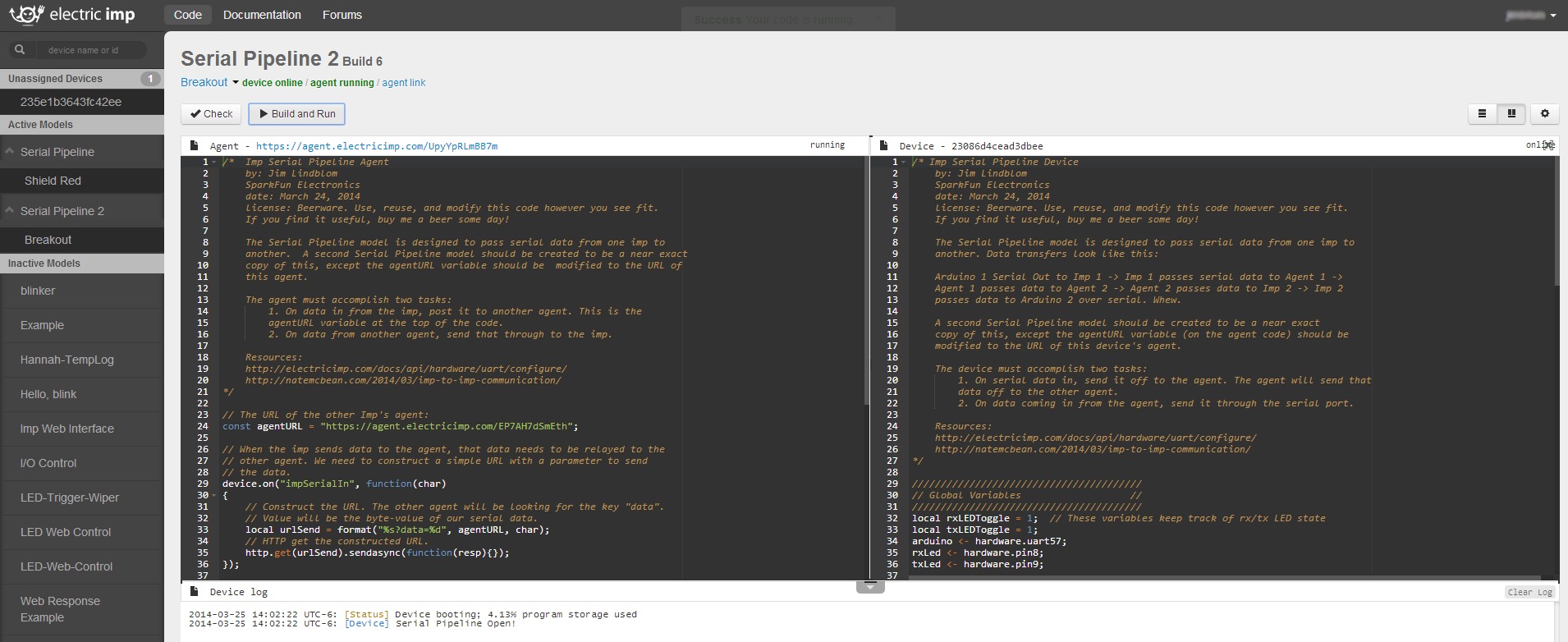
To communicate between a pair of Imp/agent's you'll need two separate active models. So create a second model (we named ours "Serial Pipeline 2") and copy the same two pieces of code into that, except set the agentURL variable in the second agent to that of the first.
Click the example image above to see our example setup. Note there are two active models -- "Serial Pipleine" and "Serial Pipeline 2" -- and two separate Imp devices under those.
Arduino Sketch
Our Arduino sketch will set up something of a terminal chat program. Any data sent to the Arduino from the Serial Monitor, will be read by the Arduino and sent out a second, software, serial port to the Imp. Serial data sent from the Imp to the Arduino is read and sent out to the Serial Monitor.
Here's the example sketch. Feel free to copy/paste, or click here to download a full copy:
language:c
/* Electric Imp-to-Arduino Serial Pipeline
  by: Jim Lindblom
  SparkFun Electronics
  date: March 24, 2014
  license: Beerware. Use, reuse, and modify this code however you see fit.
  If you find it useful, buy me a beer some day!

  This sketch is part of the Electric Imp Serial Pipeline code.
  This is a simple, SoftwareSerial-to-hardware serial sketch.
  Anything piped through the hardware serial port will be routed
  out the software serial. And vice-versa for software-to-
  hardware.

  Hardware Hookup:
  Arduino -------- Imp
    GND ---------- GND
    3.3V --------- 3V3
    8 ------------  5 (Imp Tx)
    9 ------------  7 (Imp Rx)
  Imp also has two LEDs (optionally) tied to pins 8 and 9, which
  indicate serial RX's and TX's. LEDs are connected to be active-
  low (anode connected to 3.3V).

  Same as shield schematic:
http://cdn.sparkfun.com/datasheets/Dev/Arduino/Shields/electric-imp-shield-v11.pdf

*/

#include <SoftwareSerial.h>

const int IMP_SERIAL_RX = 8;
const int IMP_SERIAL_TX = 9;

// Create an instance of software serial.
SoftwareSerial impSerial(IMP_SERIAL_RX, IMP_SERIAL_TX);

void setup()
{
 // Open the hardware serial port
  Serial.begin(19200);

  // set the data rate for the SoftwareSerial port
  impSerial.begin(19200);
}

void loop() // run over and over
{
  // Send data from the software serial
  if (impSerial.available())
    Serial.write(impSerial.read());  // to the hardware serial
  // Send data from the hardware serial
  if (Serial.available())
    impSerial.write(Serial.read());  // to the software serial
}
The software serial library (included with Arduino) is used is setup pins 8 and 9 as Arduino's RX and TX, respectively. Those pins come pre-wired on the Imp Shield. Using the RedBoard, we have to use SoftwareSerial because the hardware serial port is connected to the USB-to-Serial chip, which we'll need for the Serial Monitor.
Testing Out the Chat
Now all that's left is testing the chat system out. Open up terminals for each of the Arduinos. You may need to use a terminal program (like HyperTerminal, TeraTerm, etc.) in addition to the Serial Monitor, as it seems you can't open up Serial Monitors on multiple ports.
Try sending something to your Arduino. Pretty instantaneously you should see the TX then RX LEDs blink on the shields, and whatever you typed should end up in the other terminal window!
Okay, we can admit this is a little silly. Just think about the journey that “Hello, World” had to take just to get from one serial port to the other. It went through the Imp, out your WiFi, into a magical cloud on a server far far away, then it completed the round trip back to your WiFi and into the other Imp. We've come a long way from null-modem serial cables.
But, just imagine what this could be! All you need is an internet-connected WiFi. There's nothing that says these Imps have to be on the same WiFi network, or even in the same country. You could have an Arduino/Imp combo connected to a coffee shop WiFi in Seoul, seamlessly passing data to an Arduino/Imp combo sitting here connected to the SparkFun WiFi. Even chatting with an Arduino 10 miles away at my house seems pretty darn cool.
Resources and Going Further
We had to update this tutorial after Electric Imp drastically updated their IDE. Some of this code was based off examples written by Nate McBean. Thanks a bunch, Nate!
If you're looking for other Imp resources, here are some of our favorite:
- electric imp API Reference - Here you'll find all of the imp-specific functions.
- electric imp Developer Forums - There's a wealth of knowledge in the imp community. If you've got a question, search for an answer here, or start a new topic.
- Imp Card Spec Sheet - A good datasheet for the imp. You'll find electrical characteristics here, along with other useful info.
If you're still left with imp-related questions, try consulting their forums.
Going Further
Now that you know how to hook up the electric imp and its Breakout, what project will you be making with it? Will you be adding to the "Internet of Things"? Need some inspiration? Check out some of these products and projects:
- Wireless Arduino Programming with Electric Imp -- Use the Electric Imp to reprogram your Arduino over the Internet.
- Weather Station Wirelessly Connected to Wunderground -- Take this tutorial one step further, and find out how to use an Imp to post weather data collected by an Arduino.
- Making Simon Says Wireless -- If you're on a wireless kick, this tutorial will show you how to "hack" our Simon Says kit to make it wireless.