Shapeoko Assembly Guide
 MTaylor
 Assembly
Follow the Shapeoko assembly instructions until you get to the part where controller is added. There are a few differences, for instance the motors in this kit have equal length wires, but nothing too significant. Use the parts list from downloaded from the "Required Materials" section above rather than the list from the assembly guide.
Set Aside Some Time It may take about four hours to complete the initial assembly. Once you've got it, continue on.Install the Shapeoko into the enclosure. There are 10 4-40 screws for this purpose, but you'll only need 8. Use a number 1 phillips screwdriver.
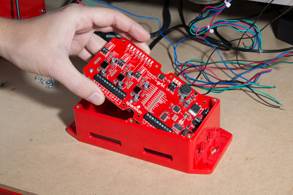
To get the Stepoko into the enclosure, put the 'port end' in first. 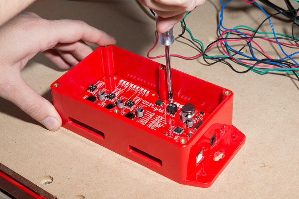
Installing the 4-40 screws Get ready to install the controller. Test fit it first, but don't install just yet, set it down such that the pad can be added, and then it can be rotated into position. Make sure the aluminum heatsink and extruded mill rail are clean and free of debris.
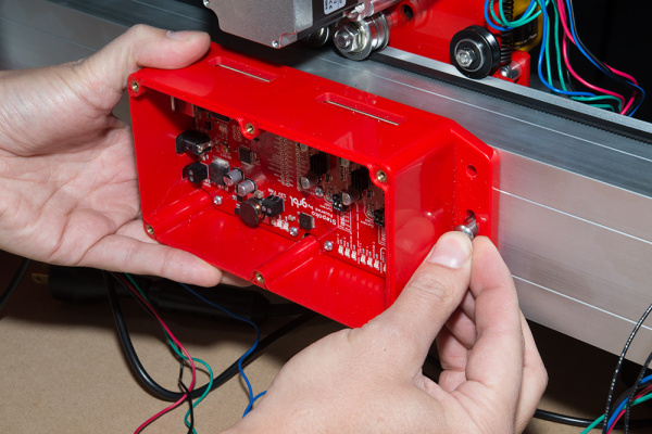
Test fitting the enclosure -- the motor wires will go through the top 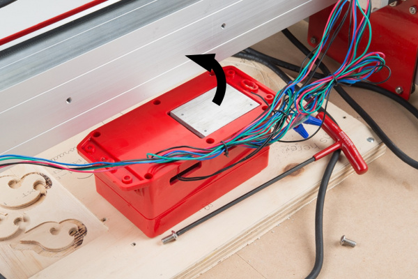
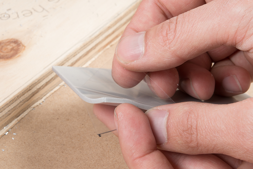
Here the enclosure is ready to rotate up onto the mill into the correct orientation. This picture is shown with the wires installed. Don't worry if yours are not installed yet, that will be covered later. Peel one side's protective sheet away and discard. Both sides will be removed, but just peel one for now.

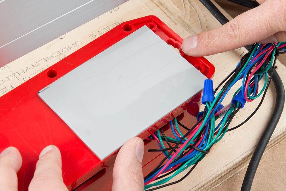
Peeling the protective sheet. Once removed, the rigidity of the material changes completely Holding by the corners, lower the pad onto the exposed heat sink, and gently press into place. Generally, it just needs to be centered and overlapping the edge of the heat sink. It's been sized so that the following two points can insure it's in the correct position:
- The long edge is flush with the enclosure's edge, towards the motor wires.
- The short edge is flush with the keyholed mounting hole.
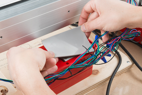
Lowering the pad 
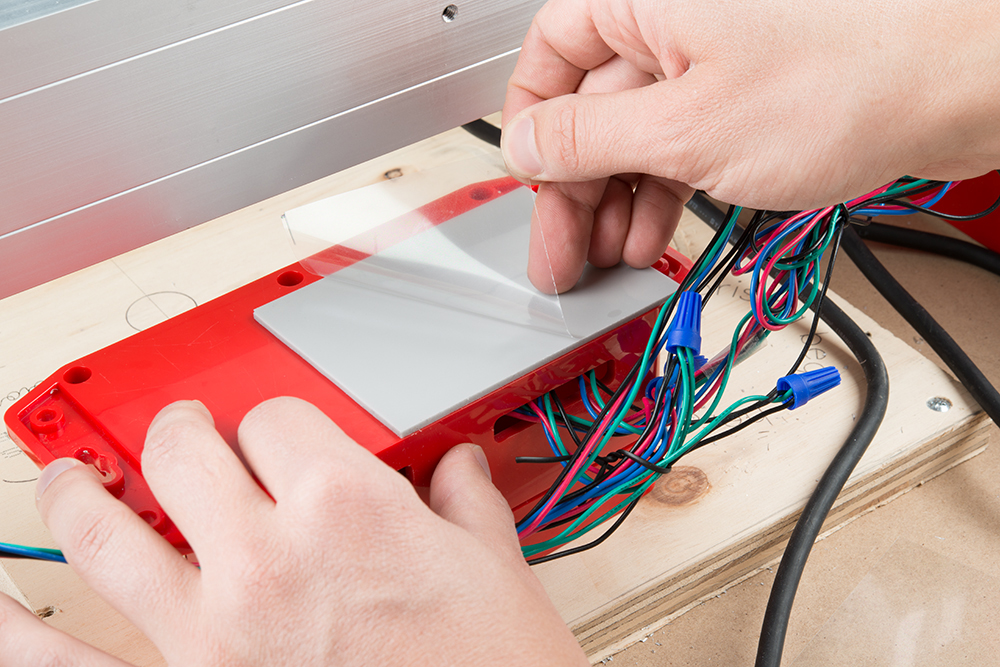
Checking for proper alignment. Here, my thumb checks flushness on one edge while I point out the proper alignment near the mounting hole. Peel the second protective layer away.

Removing the protective sheeting Install the Stepoko controller. The pad will add thickness and cause the enclosure to sit off the mill, so don't tighten the mounting bolts down too hard. Use threadlocker to keep the screw from backing out due to vibrations. Alternately, a flat washer that's slightly thinner than the pad can be used here.
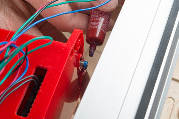
Applying threadlocker -- Here, a bit too much is used. It only needs to be filling in the treads. Excess may run. 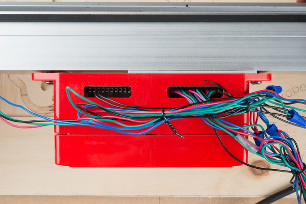
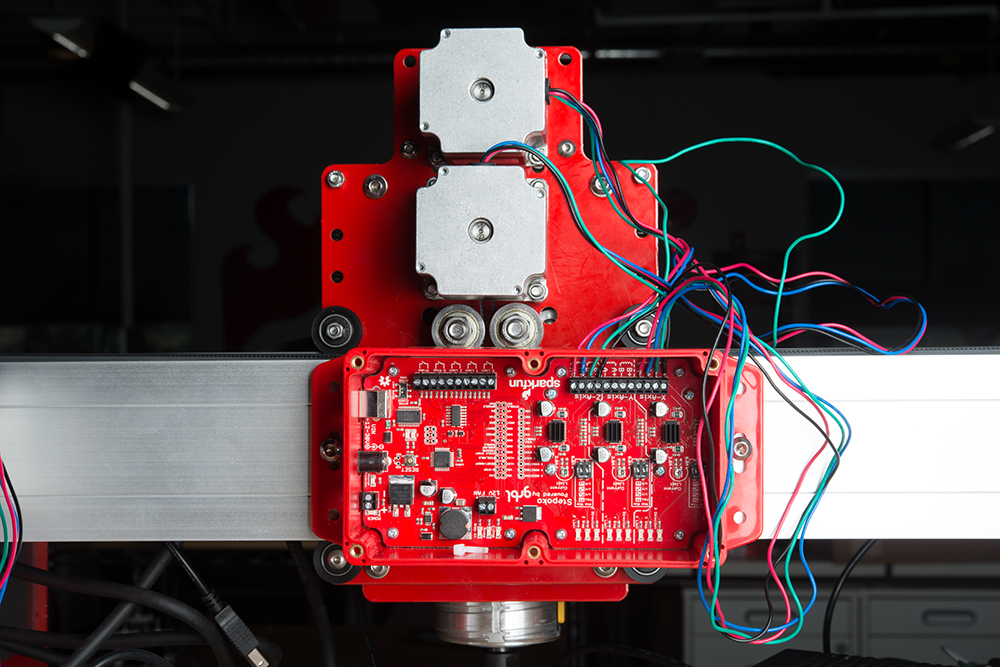
The finished installation. Notice that the enclosure is nice and even and not deformed along the mill. Install the enclosure to the rail with the terminal connections at the top. Use the extra M6x12mm bolts provided with the Shapeoko.
Connect the X and Z axes to the Stepoko. For more information, check the Stepoko guide's Hardware: Connecting the Motors section.
- Tin the wire ends with some solder.
- Identify which pairs of wire are connected inside the motors with your meter.
- Match the coils to the winding symbols on the Stepoko. Either polarity or A-B position will work, but may make the motors spin the other way. This can be changed in software.
The X and Z axis are connected. Connect the Y axis. But wait! It has two motors that are wired in parallel.
If two stepper motors are connected in parallel, they may not spin in the same direction because the internal polarities may not be the same. The solution to this problem is to transpose the colors of one pair of coil wires. This polarity/spin direction problem is compounded by the fact that the motors are mirrored on the mill and actually need to spin different directions.
Watch the video below go get a basic idea, then work through these steps.
- Connect short leads to the Y axis terminals.
- Identify the coils.
- Group one coil from each motor together by color, except with reversed polarities.
- Twist the ends to test.
- Try and move the mill in the Y axis. If it moves smoothly, solder the wires and apply heatshrink/electrical tape, or use wire nuts.
- If the axis moved roughly, unlike the X and Z axes, filp one of the pairs of coils so that it has the same colors combined, but leave the other reversed. This is because the motor's coils are not always wired the same internally.
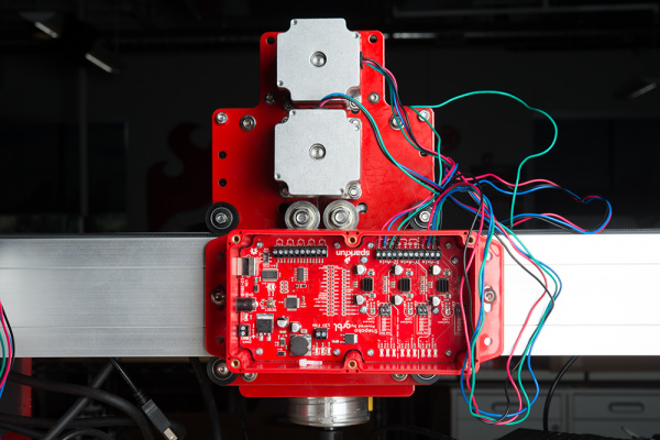
Take a quick look at this video to see, and hear, how the Y axis when wired incorrectly, and correctly. Set the motor drive currents. Make sure the trimpots are in the center for 1A service until you are more experienced. Or, read up on how the current setting works in the Stepoko Guide's Hardware: Setting the current section.
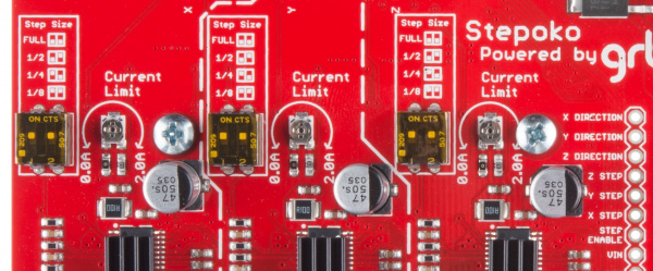
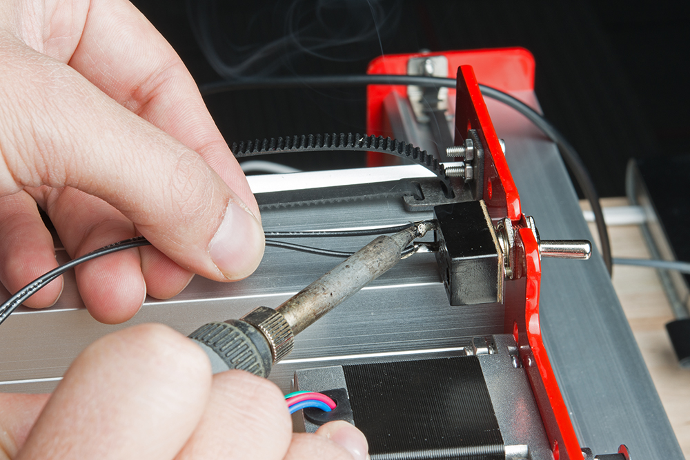
The trimpots are centered for 1 A drive in this photograph. Mount the switch to a free hole on the gantry end plate and solder on leads.
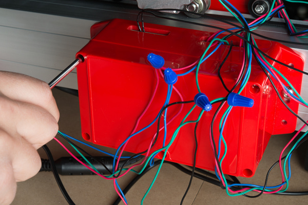
Here the switch has been mounted and the switch wires are being measured. They go into the two terminals labled E-Stop. 
Soldering on the leads. 
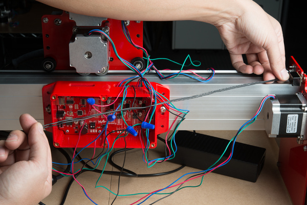
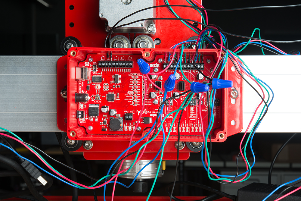
All of the wires are added for this mill setup. Screw in the lid to the enclosure using a number 1 or 2 phillips.
Collect your wires and bind with twist ties or zip ties.
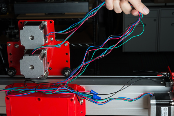
The Y axis wires have been twist tied together here. The X and Z axes are gently pulled out to see how long they are. 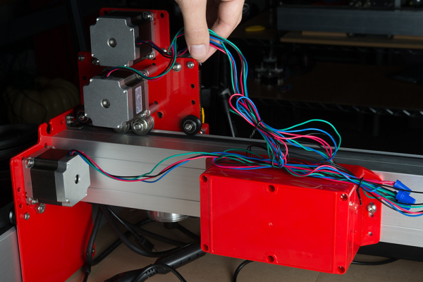
With the X axis moved ofer to one end, I can see that my bound wires have enough slack so that they won't be pulled on when the carriage moves. Caution: If milling conductive materials, be sure to seal up the openings where the wires pass through. Conductive dust that enters the enclosure can short out the circuits.Connect the power supply, power cord, and USB cord between your computer and the Stepoko
Open up the Universal Gcode Sender, open the Stepoko's serial port, and select the machine control tab. Set the switch to 'ON' and try to move the machine by computer control. If the axis move in the wrong directions to your liking (but of course, up should be positive Z), switch the direction bit field accordingly. Use the Stepoko guide's Software: Machine Control section for more information about grbl, or check out grbl's Github wiki for more information on changing settings.
Measure know movements and calibrate each axis. See the Stepoko guide's Firmware: Configuring grbl and Calibrating section for more info.


