Serial Controlled Motor Driver Hookup Guide
 MTaylor
Hardware Overview
This section describes the basic parts of the hardware.

Power is supplied through the VIN Connection and is regulated down to 3.3V for the PSoC and logic circuits. A VCC rail pin is provided for hackability.
The Status LED has a few things that it displays simultaneously:
- Emits a blip when it receives data from the controller.
- Flashes once every ~2.5 seconds to indicate nominal condition
- Flashes eight times per ~2.5 second period to indicate that the failsafe condition has occurred.
The User Port is designated for connection to the user's project (which will tell the motors what to do), and can be configured as UART, SPI, or I2C by jumper setting.
The Expansion Port is configured as I2C controller or peripheral based on jumper settings, and operates on a second I2C bus with only other motor drivers.
The microcontroller generates PWM signals that go straight to the DRV8835 motor driver, which consists of 2 mosfet H-bridge driver circuits with thermal and current protection built in.
Powering the SCMD
Provide 3.3V to 11V to "MAX 11V" and "GND". Each has two through-holes for general use. They can be used to reduce connection resistance or to piggyback other devices, or can accept the leads of a large capacitor. The terminal is directly connected to the DRV8835's power input, and is also regulated down to 3.3V for the PSoC supply and logic levels. The driver can consume up to 3A of current so make sure these wires are short or heavier gauge, or both.
When peripherals are attached to the expansion port, they also require power from another source. Wire the "MAX 11V" and "3.3V" pins in parallel with the controller as shown in Expansion Port Usage.
The VCC pin is an advanced feature that can be used to operate the SCMD at a different voltage, but isn't used for basic applications. See the SCMD Datasheet for more information.
Jumper Usage Table
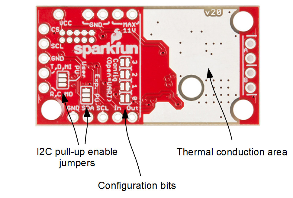
There are 4 sets of jumpers to configure on this board. There are pull-up enables for both user (User PU) and expansion bus (Exp. PU, default not-pulled up), A VCC disconnect jumper (VCC Src) to remove all logic from the on-board regulator, and 4 config bits that select operational mode.
| Name | Description | Usage |
|---|---|---|
| VCC Src | Connects VCC rail (pin) to on-board regulator | Open to remove regulator from VCC rail. User must supply 1.8V to 5.5V to VCC pin |
| User PU | I2C pull-up enable for User Port | Close all three pads to connect 4.7k resistors to SDA and SCL of user port |
| Exp. PU | I2C pull-up enable for Expansion Port | Close all three pads to connect 4.7k resistors to SDA and SCL of expansion port. The expansion bus should have exactly one board with pull-ups enabled on it. A single controller without peripherals is technically a complete expansion bus, and thus the single controller needs these jumper pads bridged. |
| Config | Serial and function selection | The config bits are 4 bits that form a configuration nybble. A closed jumper is a '1' and an open jumper is a '0'. See config table for more information. |
Config Bits Table
The configuration is set by encoding a number into the 4 config bits on the bottom of the board. Close a jumper to indicate a 1, or leave it open to indicate a 0. Use this table to see what the user port, address, and expansion port will become in each configuration.
| Pattern | Mode | User Port | User Address | Expansion Port |
|---|---|---|---|---|
| 0000 | UART at 9600 | UART | N/A | Controller |
| 0001 | SPI | SPI | N/A | Controller |
| 0010 | Peripheral | N/A | N/A | Peripheral |
| 0011 | I2C | I2C | 0x58 | Controller |
| 0100 | I2C | I2C | 0x59 | Controller |
| 0101 | I2C | I2C | 0x5A | Controller |
| 0110 | I2C | I2C | 0x5B | Controller |
| 0111 | I2C | I2C | 0x5C | Controller |
| 1000 | I2C | I2C | 0x5D | Controller |
| 1001 | I2C | I2C | 0x5E | Controller |
| 1010 | I2C | I2C | 0x5F | Controller |
| 1011 | I2C | I2C | 0x60 | Controller |
| 1100 | I2C | I2C | 0x61 | Controller |
| 1101 | UART at 57600 | UART | N/A | Controller |
| 1110 | UART at 115200 | UART | N/A | Controller |
| 1111 | N/A | Reserved | N/A | N/A |
Pin Connections
The function of the 0.1" holes are explicitly indicated in this table, and are organized by physical location on the PCB.
| Function / Connection | ||||||
|---|---|---|---|---|---|---|
| Group | Name | Direction | Description | UART | I2C | SPI |
| User Port | RX,SCL,COPI | I | Multi-function Serial | Data In (RX) | SCL | COPI |
| TX,SDA,CIPO | IO | Multi-function Serial | Data Out (TX) | SDA | CIPO | |
| GND | - | Ground | Ground | Ground | Ground | |
| NC,SCL | I | SPI clock | NC | NC | SCL | |
| NC,CS | I | SPI chip select | NC | NC | CS | |
| Expansion Port | GND | - | Ground | Peripheral bus Ground | ||
| SDA | IO | I2C Data line | Peripheral bus SCL | |||
| SCL | I | I2C Clock line | Peripheral bus SDA | |||
| In | I | Config In. Peripheral aquire-address/enable | Connects to upstream peripheral* | |||
| Out | O | Config Out. Enable next peripheral | Connects to downstream peripheral* | |||
| Motor Port | A1 | O | Winding of first addressable location | Motor A winding | ||
| A2 | O | Winding of first addressable location | Motor A winding | |||
| B1 | O | Winding of second addressable location | Motor B winding | |||
| B2 | O | Winding of second addressable location | Motor B winding | |||
| Power | GND | I | Main system ground (two pads) | Supply ground | ||
| MAX 11V | I | Motor driver raw voltage, regulator in (two pads) | Supply power | |||
| VCC | IO | Regulator output or user supplied VCC | NC | |||
Typical Application Motors and Heat Sinking
The SCMD is designed to operate small robot drive motors without a heatsink, up to about 500mA continuous current. Here's how some regular motors fair when used.
- Hobby Gearmotor - 200 RPM (Pair) -- RedBot style motors. These have low stall current and can be used without heatsinks.
- Micro Gearmotor - 460RPM -- These can be used without heatsinks.
- Standard Gearmotor - 303RPM -- Motors of this larger size can also be used without heatsinks.
- CPU fans -- can be varied. Include a forward diode to prevent reverse voltage application. Some can draw a large amount of current! If the driver is getting too warm, a heatsink (or forced air) is required.
- Vacuum Pump - 12V -- These pumps can draw amps. The driver will need to have heatsinking.
Determining if a heat sink is necessary
The temperature rise is related to the current load on the motor driver. To determine what your load is, attach the motor directly to a power supply and apply torque as will be done by the final application. Then use the chart below to determine if you need to heat sink. You can also stall the motor completely and measure the stall current (or use a multimeter to check the coil resistance, then do the math).
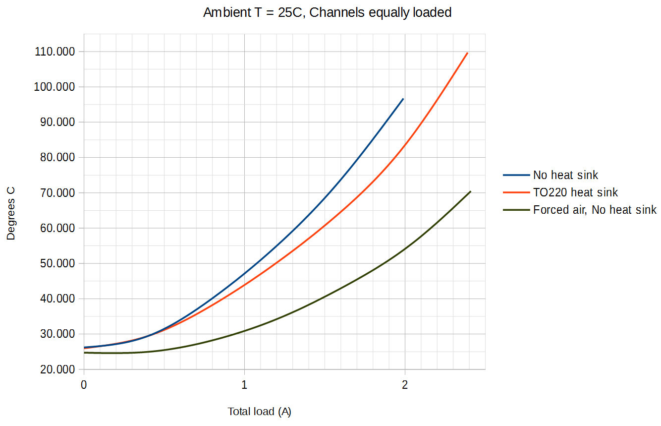
This graph shows total current sourced by the SCMD from both channels. If using bridged mode, find your target current load on the X axis, then see what to expect from these configurations on the Y axis. If not using bridged mode, double the current of a single motor to find the worst case condition of both motors at max current, then use that instead.
The TO-220 Heat Sink and Theragrip Thermal Tape were used to make the above graph, and work well to give yourself an extra amp of capability in a typical application.