Serial Controlled Motor Driver Hookup Guide
 MTaylor
Example 3: Two Peripherals, 5 motors, 1 bridged (SPI control)
This demonstrates more advanced usage of the serial driver. Here, we have a couple peripherals attached, with one being configured as a bridged mode. This is a good example of how the motor numbering scheme works.
Requirements
- SparkFun RedBoard or Arduino compatible 328p device
- The Arduino Library
- A Logic Level Converter
- Controller config jumpers set to '0001', or only position '0' closed.
- Peripheral config jumpers set to '0010', or only position '1' closed.
- Exp. PU jumper fully closed

Connections
Connect the Arduino and Level Shifter to the motor drvier as follows. This connects to the standard SCL, COPI, and CIPO positions, and uses pin 10 as a chip select.
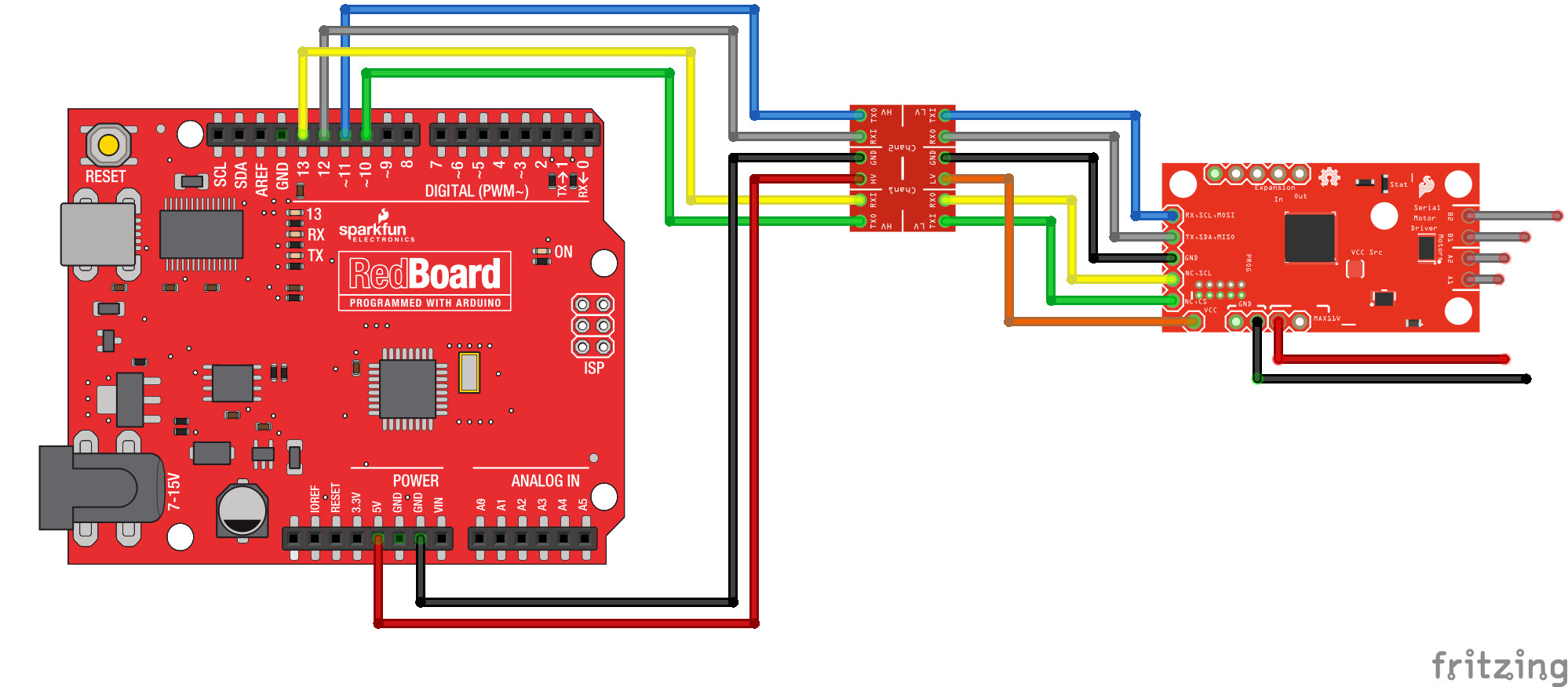
While this example will operate with only a controller, add peripherals to the expansion port to get the full experience.
The expansion port allows multiple SCMDs to be run from the same I2C address, SPI select line, or UART instance. The port can support up to 16 SCMDs set as peripheral by a common I2C interface, and daisy-chained config-in to config-out wiring
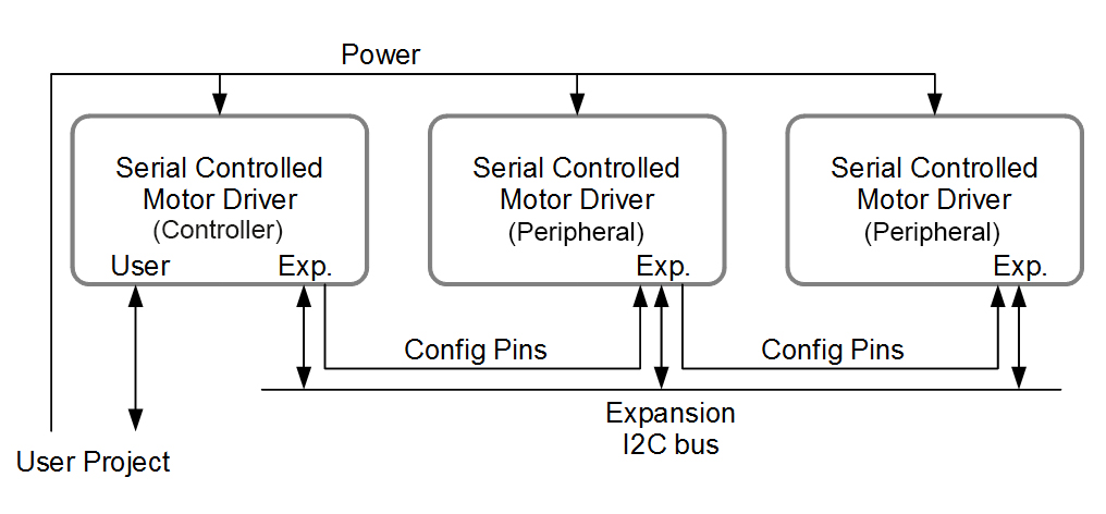
Notice that the expansion I2C lines are connected to a common bus while the config lines are connected from one board's 'Out' to the next's 'In'. More peripherals can be added onto the end of the chain.

When power is applied, the controller will assign addresses to the peripherals. This may take a couple seconds. When complete, the peripherals should all have a faintly lit, blinking status LED indicating communication.
Example Code
The example, also available from the drop-down menu in Arduino (It's called DriverChainWithBridging), is as follows:
language:c
//This example demonstrates some of the more advanced usage of the motor driver.
//It uses 3 motor drivers, with the controller attached as SPI.  One peripheral is bridged,
//and the sketch test drives each motor. (There will be a break when the overtaken motor
//channel is activated.)
//
//This also shows how to count the number of connected peripherals and report, as well as
//arbitrary register access.

#include <Arduino.h>
#include <stdint.h>
#include "SCMD.h"
#include "SCMD_config.h" //Contains #defines for common SCMD register names and values
#include "Wire.h"

//#defines

//Variables
//***** Create the Motor Driver object*****//
SCMD myMotorDriver;

void setup()
{
  Serial.begin(9600);

  Serial.println("Starting sketch.");

  //***** Configure the Motor Driver's Settings *****//

  //  .commInter face can be I2C_MODE or SPI_MODE
  myMotorDriver.settings.commInterface = I2C_MODE;
  //myMotorDriver.settings.commInterface = SPI_MODE;

  //  set address if I2C configuration selected with the config jumpers
  myMotorDriver.settings.I2CAddress = 0x5A; //config pattern "0101" on board for address 0x5A
  //  set chip select if SPI selected with the config jumpers
  myMotorDriver.settings.chipSelectPin = 10;

  delay(2500); //Give the serial driver time to check for peripherals

  //  initialize the driver and enable the motor outputs
  uint8_t tempReturnValue = myMotorDriver.begin();
  while ( tempReturnValue != 0xA9 )
  {
    Serial.print( "ID mismatch, read as 0x" );
    Serial.println( tempReturnValue, HEX );
    delay(500);
    tempReturnValue = myMotorDriver.begin();
  }
  Serial.println( "ID matches 0xA9" );

  Serial.print("Waiting for enumeration...");
  while ( myMotorDriver.ready() == false );
  Serial.println("Done.");

  //  Report number of peripherals found
  uint8_t tempAddr = myMotorDriver.readRegister(SCMD_SLV_TOP_ADDR);
  if ( tempAddr >= START_SLAVE_ADDR )
  {
    Serial.print("Detected ");
    Serial.print(tempAddr - START_SLAVE_ADDR + 1); //Top address minus bottom address + 1 = number of peripherals
    Serial.println(" peripherals.");
  }
  else
  {
    Serial.println("No peripherals detected");
  }

  //Configure bridging modes
  myMotorDriver.bridgingMode( 1, 1 ); //( DriverNum 1, bridged state = 1 )  This will bridge the first peripheral

  //Uncomment to set inversion

  //myMotorDriver.inversionMode(0, 1); //invert controller, channel A
  //myMotorDriver.inversionMode(1, 1); //invert controller, channel B
  //myMotorDriver.inversionMode(2, 1); //invert peripheral 1, channel A
  //    no need to configure motor 3, this position does nothing because the peripheral is bridged.
  //myMotorDriver.inversionMode(4, 1); //invert peripheral 2, channel A
  //myMotorDriver.inversionMode(5, 1); //invert peripheral 2, channel B

  //Enable the motors.
  myMotorDriver.enable();

  pinMode(8, INPUT_PULLUP);

}

void loop()
{
  //***** Operate the Motor Driver *****//
  //  This walks through all 34 motor positions driving them forward and back.
  //  It uses .setDrive( motorNum, direction, level ) to drive the motors.
  //
  //  Notice that when i == 3, no motor spins.  This position is made inactive by bridging the first peripheral.
  Serial.println("Now stepping through the motors.");
  for (int i = 0; i < 6; i++)
  {
    Serial.print("Driving motor ");
    Serial.println(i);

    myMotorDriver.setDrive( i, 1, 255); //Drive motor i forward at full speed
    delay(1000);
    myMotorDriver.setDrive( i, 0, 255); //Drive motor i backward at full speed
    delay(1000);
    myMotorDriver.setDrive( i, 1, 0);
  }
}
The example works by counting through the 6 motor positions and commanding them forward, then back.
Things to note:
- Only a single SCMD object is used, all peripherals are accessed through the controller.
- begin is periodically ran until the returned ID word is valid.
- Setup waits for isReady() to become true before going on to the drive section
- Peripherals are counted by directly accessing the registers. ALL_CAPS_VALUES are #defined in SCMD_config.h.
- bridgingMode( ... ) is called to bridge, by number of motor driver (controller is driver 0).
- Motor 3 is excluded because the channel gets connected to motor 2 by brdiging. Though it can still be commanded, it will have no effect.
- enable() is called to activate the motors. This happens after the bridging configuration is set to protect the drivers.