Serial Controlled Motor Driver Hookup Guide
 MTaylor
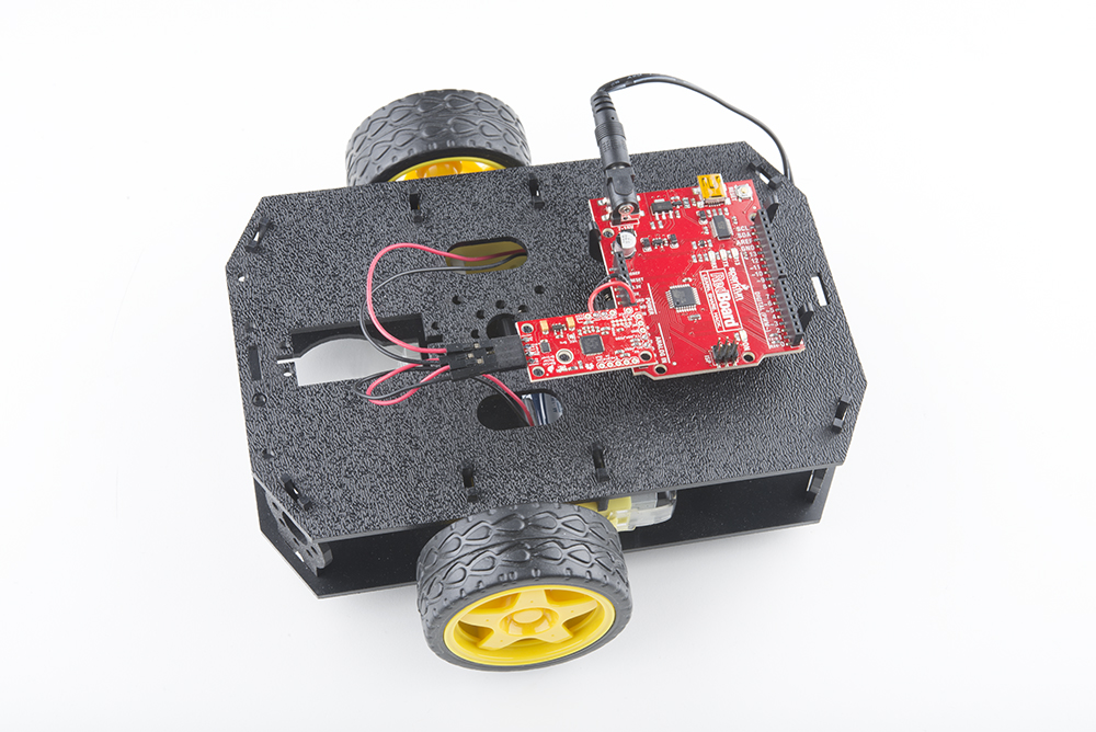
Example 2: RedBot Retrofit (I2C control)
This example drives a robot in left and right arcs, driving in an overall wiggly course. It demonstrates the variable control abilities. When used with a RedBot chassis, each turn is about 90 degrees per drive.
Requirements
- SparkFun RedBoard or Arduino compatible 328p device
- The Arduino Library
- Config jumpers set to address 0x5A, or '0101', or positions 0 and 2 closed with 1 and 3 open. Other addresses can be selected by using the bit patters of 0x3 to 0xE, and appropriate address programmed into the 328p code.
- User PU jumper fully closed
- Exp. PU jumper fully closed
The 328p is now ready to communicate with the SCMD. Skip forward to the Arduino Library section for API usage, or use one of the example sketches.

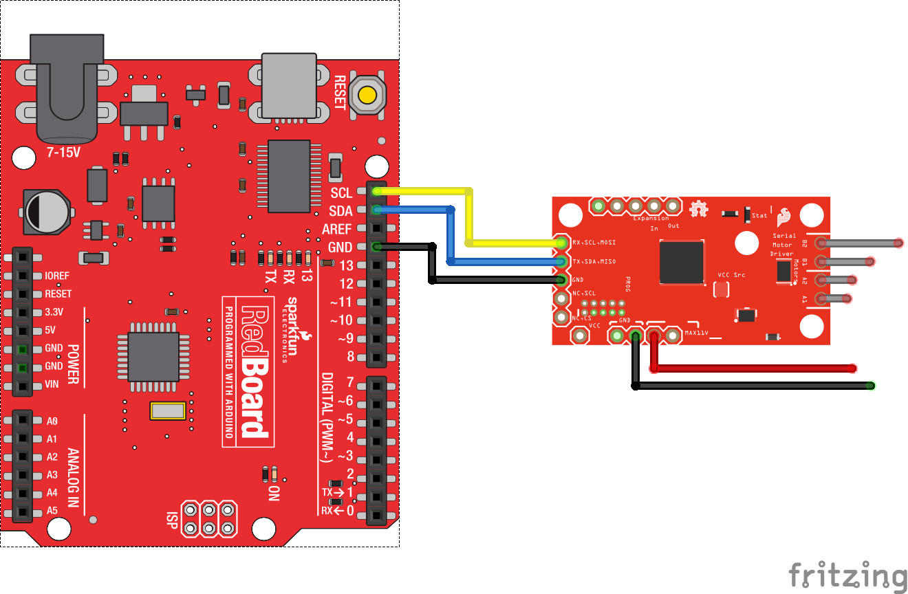
Connections
Connect the Arduino basic to the motor drvier as follows. The SDA and SCL pins are pulled up by the SCMD only, and should idle at 3.3V.
Example Code
The example, also available from the drop-down menu in Arduino (It's called TwoMotorRobot), is as follows:
language:c
//This example drives a robot in left and right arcs, driving in an overall wiggly course.
//  It demonstrates the variable control abilities. When used with a RedBot chassis,
//  each turn is about 90 degrees per drive.
//
//  Pin 8 can be grounded to disable motor movement, for debugging.

#include <Arduino.h>
#include <stdint.h>
#include "SCMD.h"
#include "SCMD_config.h" //Contains #defines for common SCMD register names and values
#include "Wire.h"

SCMD myMotorDriver; //This creates the main object of one motor driver and connected peripherals.

void setup()
{
  pinMode(8, INPUT_PULLUP); //Use to halt motor movement (ground)

  Serial.begin(9600);
  Serial.println("Starting sketch.");

  //***** Configure the Motor Driver's Settings *****//
  //  .commInter face can be I2C_MODE or SPI_MODE
  myMotorDriver.settings.commInterface = I2C_MODE;
  //myMotorDriver.settings.commInterface = SPI_MODE;

  //  set address if I2C configuration selected with the config jumpers
  myMotorDriver.settings.I2CAddress = 0x5A; //config pattern "0101" on board for address 0x5A

  //  set chip select if SPI selected with the config jumpers
  myMotorDriver.settings.chipSelectPin = 10;

  //*****initialize the driver get wait for idle*****//
  while ( myMotorDriver.begin() != 0xA9 ) //Wait until a valid ID word is returned
  {
    Serial.println( "ID mismatch, trying again" );
    delay(500);
  }
  Serial.println( "ID matches 0xA9" );

  //  Check to make sure the driver is done looking for peripherals before beginning
  Serial.print("Waiting for enumeration...");
  while ( myMotorDriver.ready() == false );
  Serial.println("Done.");
  Serial.println();

  //*****Set application settings and enable driver*****//

  //Uncomment code for motor 0 inversion
  //while( myMotorDriver.busy() );
  //myMotorDriver.inversionMode(0, 1); //invert motor 0

  //Uncomment code for motor 1 inversion
  while ( myMotorDriver.busy() ); //Waits until the SCMD is available.
  myMotorDriver.inversionMode(1, 1); //invert motor 1

  while ( myMotorDriver.busy() );
  myMotorDriver.enable(); //Enables the output driver hardware

}

#define LEFT_MOTOR 0
#define RIGHT_MOTOR 1
void loop()
{
  //pass setDrive() a motor number, direction as 0(call 0 forward) or 1, and level from 0 to 255
  myMotorDriver.setDrive( LEFT_MOTOR, 0, 0); //Stop motor
  myMotorDriver.setDrive( RIGHT_MOTOR, 0, 0); //Stop motor
  while (digitalRead(8) == 0); //Hold if jumper is placed between pin 8 and ground

  //***** Operate the Motor Driver *****//
  //  This walks through all 34 motor positions driving them forward and back.
  //  It uses .setDrive( motorNum, direction, level ) to drive the motors.

  //Smoothly move one motor up to speed and back (drive level 0 to 255)
  for (int i = 0; i < 256; i++)
  {
    myMotorDriver.setDrive( LEFT_MOTOR, 0, i);
    myMotorDriver.setDrive( RIGHT_MOTOR, 0, 20 + (i / 2));
    delay(5);
  }
  for (int i = 255; i >= 0; i--)
  {
    myMotorDriver.setDrive( LEFT_MOTOR, 0, i);
    myMotorDriver.setDrive( RIGHT_MOTOR, 0, 20 + (i / 2));
    delay(5);
  }
  //Smoothly move the other motor up to speed and back
  for (int i = 0; i < 256; i++)
  {
    myMotorDriver.setDrive( LEFT_MOTOR, 0, 20 + (i / 2));
    myMotorDriver.setDrive( RIGHT_MOTOR, 0, i);
    delay(5);
  }
  for (int i = 255; i >= 0; i--)
  {
    myMotorDriver.setDrive( LEFT_MOTOR, 0, 20 + (i / 2));
    myMotorDriver.setDrive( RIGHT_MOTOR, 0, i);
    delay(5);
  }
}
The example works by configuring the motor driver, then using for loops to ramp up and down the motor drive levels.
Things to note:
- begin is periodically ran until the returned ID word is valid.
- Setup waits for isReady() to become true before going on to the drive section
- One motor is inverted by command at setup. Do it here so you don't have to mess with it later.
- enable() is called to connect the drivers to the PWM generators.
- LEFT_MOTOR and RIGHT_MOTOR are defined to ease use of the setDrive( ... ) function.