RGB Panel Jumbotron
Contributors:
 b_e_n
b_e_n
b_e_n 
Hardware Hookup
Here are the pin connections between LED panel connector and the Teensy 3.1:
| Panel Pin Label | Panel Connector Pin # | Arduino Pin | Notes |
|---|---|---|---|
| R0 | 1 | 2 | Red data (columns 1-16) |
| G0 | 2 | 14 | Green data (columns 1-16) |
| B0 | 3 | 7 | Blue data (columns 1-16) |
| GND | 4 | GND | Ground |
| R1 | 5 | 8 | Red data (columns 17-32) |
| G1 | 6 | 6 | Green data (columns 17-32) |
| B1 | 7 | 20 | Blue data (columns 17-32) |
| GND | 8 | GND | Ground |
| A | 9 | 15 | Demux input A0 |
| B | 10 | 22 | Demux input A1 |
| C | 11 | 23 | Demux input A2 |
| D | 12 | 9 | Demux input E1, E3 (32x32 panels only) |
| CLK | 13 | 10 | LED drivers' clock |
| STB | 14 | 13 | LED drivers' latch |
| OE | 15 | 11 | LED drivers' output enable |
| GND | 16 | GND | Ground |
Panel connector pin numbering convention: Pin 1 is top left (R0), pin 2 is to the right of pin 1, pin 3 is below pin 1, pin 4 is to the right of pin 3, etc. Pin 16 is the bottom right.
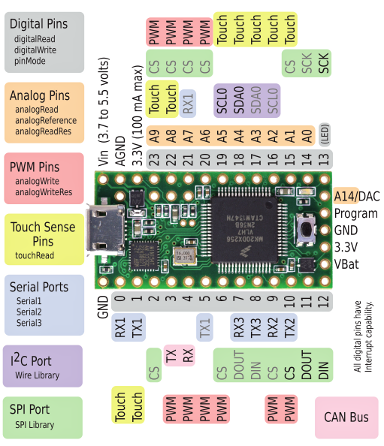
And for handy reference, here's a pinout chart for the Teensy 3.1:
When connecting into the ribbon cable connector, pay attention to the notch that signifies polarity. When looking at the cable with the notch facing up and on the left side, R0 (pin 1) should be at the top left.
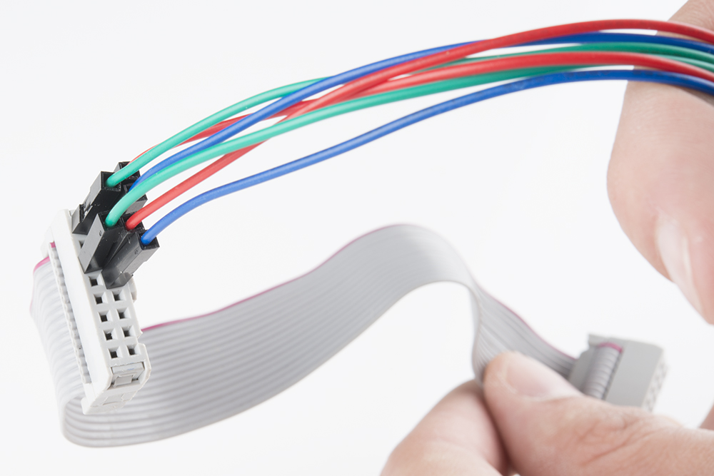
Both red and blue wires should be on the notch side, the greens should be on the other.
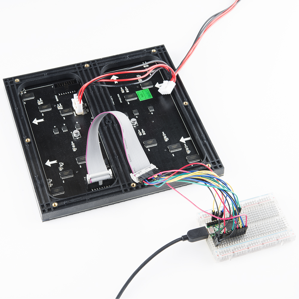
Your hardware hookup should look something like this when you're done.