RGB Panel Jumbotron
 b_e_n
b_e_n 
Introduction
If you've ever wanted to simulate live video on an array of RGB LEDs (kinda like the Jumbotron at a sports game), this tutorial is for you. Basically, we're going to take in live video from a webcam, do a little magic in Processing to translate the color values for the RGB panel, then push them out to a Teensy 3.1 Microcontroller (using the Arduino IDE), which we will program to take in the color values from Processing and turn on the proper LEDs to create a pixelated image of whatever the webcam is pointed at. Fun!
Required Materials
There are a few things you will need in order to complete this project, which are conveniently located in the wish list below:
Suggested Reading
In addition to the hardware, you may want to take a look at some background material that's relevant to this project. Here are some good links to get you started:
Setup
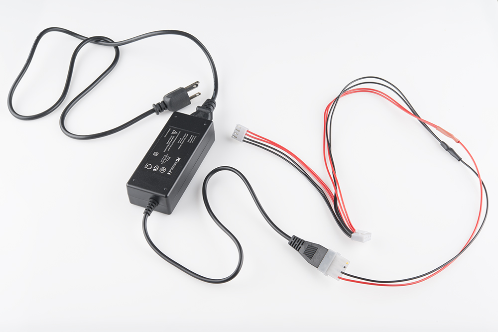
Once you've got the hardware, your first stop is our RGB Panel Hookup Guide - specifically the part about powering the panel. We'll be powering our project the exact same way, so go ahead a take a little detour over there. Note: Just do the power supply part, NOT the hardware hookup - our configuration is different.
Your power supply should look like this when finished:
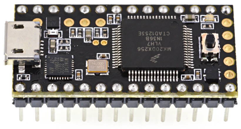
You'll also want to solder some headers (the ones in the wish list) onto your Teensy so we can stick it into a breadboard and hook it up to the RGB Panel.
We'll be programming using Processing and Arduino - so you'll want to download both of those if you don't have them already (the latest versions should work just fine). In order to program the Teensy from the Arduino IDE, you'll also need to install the Teensyduino library (instructions from the link).
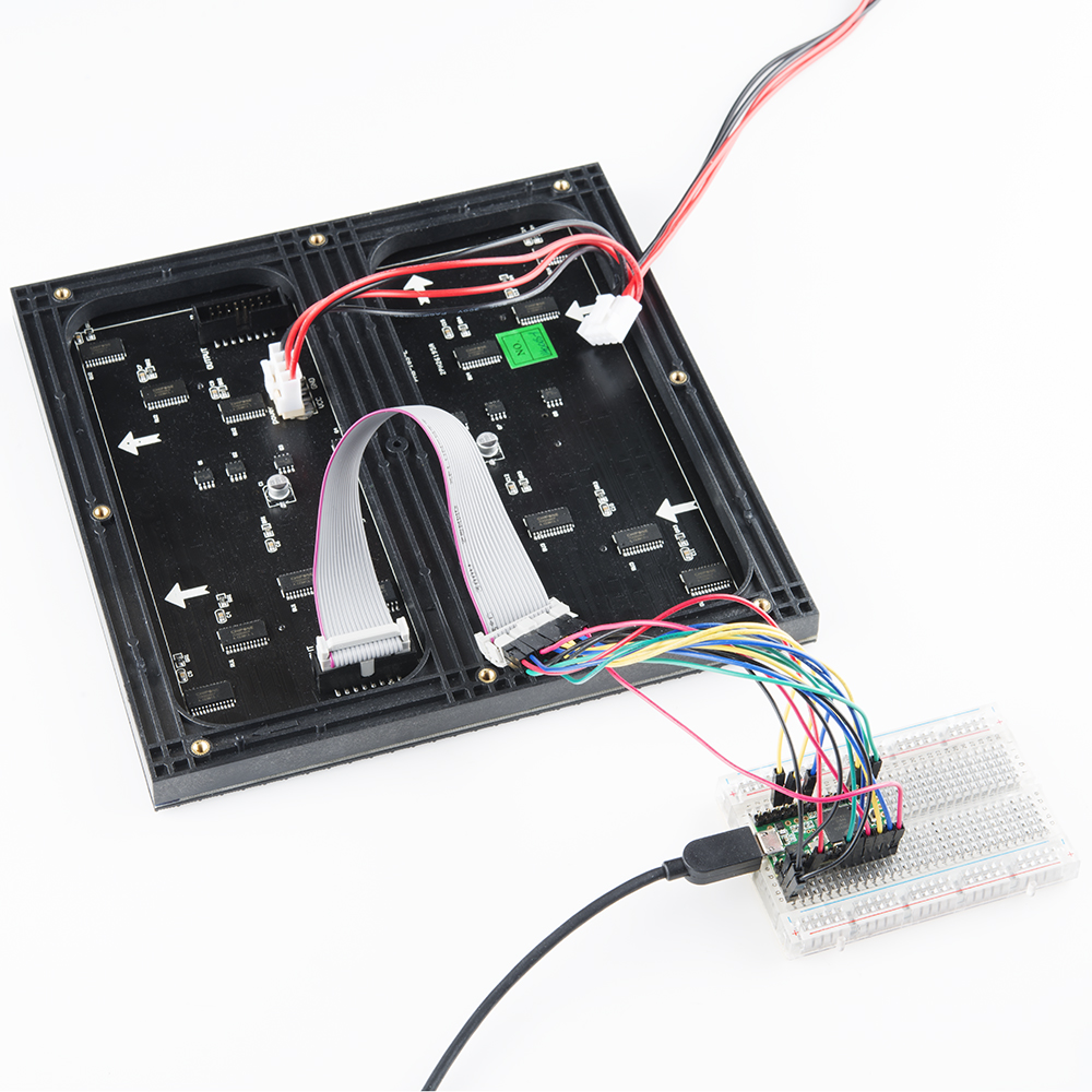
Hardware Hookup
Here are the pin connections between LED panel connector and the Teensy 3.1:
| Panel Pin Label | Panel Connector Pin # | Arduino Pin | Notes |
|---|---|---|---|
| R0 | 1 | 2 | Red data (columns 1-16) |
| G0 | 2 | 14 | Green data (columns 1-16) |
| B0 | 3 | 7 | Blue data (columns 1-16) |
| GND | 4 | GND | Ground |
| R1 | 5 | 8 | Red data (columns 17-32) |
| G1 | 6 | 6 | Green data (columns 17-32) |
| B1 | 7 | 20 | Blue data (columns 17-32) |
| GND | 8 | GND | Ground |
| A | 9 | 15 | Demux input A0 |
| B | 10 | 22 | Demux input A1 |
| C | 11 | 23 | Demux input A2 |
| D | 12 | 9 | Demux input E1, E3 (32x32 panels only) |
| CLK | 13 | 10 | LED drivers' clock |
| STB | 14 | 13 | LED drivers' latch |
| OE | 15 | 11 | LED drivers' output enable |
| GND | 16 | GND | Ground |
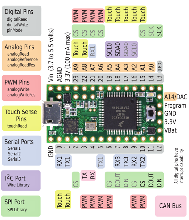
And for handy reference, here's a pinout chart for the Teensy 3.1:
When connecting into the ribbon cable connector, pay attention to the notch that signifies polarity. When looking at the cable with the notch facing up and on the left side, R0 (pin 1) should be at the top left.
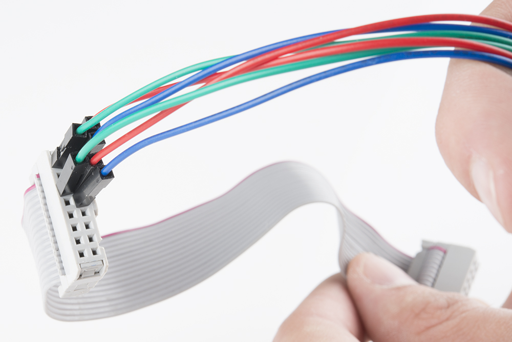
Both red and blue wires should be on the notch side, the greens should be on the other.
Teensy Code
The Teensy code is fairly long and involved, so we're just going to embed the whole thing here.
language:c
    /*
* Further modified by Ben Leduc-Mills, standing on the shoulders of those mentioned below.
*
* Modified by Markus Lipp adding interleaved buffers, streaming, 32x32 & 24bit support
*
* Based on "_16x32_Matrix R3.0" by Creater Alex Medeiros, http://PenguinTech.tk
* Use code freely and distort its contents as much as you want, just remeber to thank the
* original creaters of the code by leaving their information in the header. :)
*/

//Define pins
const uint8_t

//PortC
APIN      = 15, BPIN      = 22, CPIN      = 23, DPIN = 9,
CLOCKPIN  = 10, LATCHPIN  = 13, OEPIN     = 11,

//PortD
R1PIN     = 2, R2PIN     = 8,
G1PIN     = 14, G2PIN     = 6,
B1PIN     = 7, B2PIN     = 20;

uint8_t pinTable[13] =
{
    R1PIN, R2PIN, G1PIN, G2PIN, B1PIN, B2PIN,
    APIN, BPIN, CPIN, DPIN, CLOCKPIN, LATCHPIN, OEPIN
};

//Addresses 1/8 rows Through a decoder
uint16_t const A = 1, B = 2, C = 4, D = 8;

//Acts like a 16 bit shift register
uint16_t const SCLK   = 16;
uint16_t const LATCH  = 32;
uint16_t const OE     = 64;

//Decoder counter var
uint16_t const abcVar[16] =
{
    0, A, B, A + B, C, C + A, C + B, A + B + C,
    0 + D, A + D, B + D, A + B + D, C + D, C + A + D, C + B + D, A + B + C + D
};

//Data Lines for row 1 red and row 9 red, ect.
uint16_t const RED1   = 1, RED2   = 8;
uint16_t const GREEN1 = 2, GREEN2 = 16;
uint16_t const BLUE1  = 4, BLUE2  = 32;

const uint8_t SIZEX = 32;
const uint8_t SIZEY = 32;

//Here is where the data is all read
uint8_t interleavedBuffer[SIZEX*SIZEY * 4];

//BAM and interrupt variables
boolean actDisplay = false;
uint8_t rowN = 0;
uint16_t BAM;
uint8_t BAMMAX = 7; //now 24bit color! (0-7)


void setup()
{
    for(uint8_t i = 0; i < 13; i++)
    {
        pinMode(pinTable[i], OUTPUT);
    }
    timerInit();
    Serial.begin(250000);
}

uint8_t r, g, prevVal, val;
int dataPos = 0;

void loop()
{
    if (Serial.available())
    {
        prevVal = val;
        val = Serial.read();

        if ( (prevVal == 192 && val == 192) || dataPos >= 4096)
        {
            dataPos = 0;
        }
        else
        {
            interleavedBuffer[dataPos++] = val;
        }
    }
}

IntervalTimer timer1;

#define BAMDUR 2
void timerInit()
{
    BAM = 0;
    timer1.begin(attackMatrix, BAMDUR);
}


//The updating matrix stuff happens here
//Each pair of rows is taken through its BAM cycle,
//then the rowNumber is increased and id done again
void attackMatrix()
{
    uint16_t portData;

    //sets up which BAM the matrix is on
    if(BAM == 0)
    {
        timer1.begin(attackMatrix, BAMDUR);    //code takes max 41 microsec to complete
    }
    if(BAM == 1)
    {
        timer1.begin(attackMatrix, BAMDUR * 2);    //so 42 is a safe number
    }
    if(BAM == 2)
    {
        timer1.begin(attackMatrix, BAMDUR * 4);
    }
    if(BAM == 3)
    {
        timer1.begin(attackMatrix, BAMDUR * 8);
    }
    if(BAM == 4)
    {
        timer1.begin(attackMatrix, BAMDUR * 16);
    }
    if(BAM == 5)
    {
        timer1.begin(attackMatrix, BAMDUR * 32);
    }
    if(BAM == 6)
    {
        timer1.begin(attackMatrix, BAMDUR * 64);
    }
    if(BAM == 7)
    {
        timer1.begin(attackMatrix, BAMDUR * 128);
    }

    portData = 0; // Clear data to enter
    portData |= (abcVar[rowN]) | OE; // abc, OE
    portData &= ~ LATCH;       //LATCH LOW
    GPIOC_PDOR = portData;  // Write to Port

    uint8_t *start = &interleavedBuffer[rowN * SIZEX * 8 + ((7 - BAMMAX) + BAM) * 32];

    for(uint8_t _x = 0; _x < 32; _x++)
    {
        GPIOD_PDOR = start[_x]; // Transfer data
        GPIOC_PDOR |=  SCLK;// Clock HIGH
        GPIOC_PDOR &= ~ SCLK; // Clock LOW
    }

    GPIOC_PDOR |= LATCH;// Latch HIGH
    GPIOC_PDOR &= ~ OE; // OE LOW, Displays line


    if(BAM >= BAMMAX)   //Checks the BAM cycle for next time.
    {

        if(rowN == 15)
        {
            rowN = 0;
        }
        else
        {
            rowN ++;
        }
        BAM = 0;
        actDisplay = false;
    }
    else
    {
        BAM ++;
        actDisplay = true;
    }
}
Remember to have the board type (Teensy 3.1), USB Type (serial), and CPU Speed (96kHz overclock) set correctly under the 'Tools' menu in the Arduino IDE.
Processing Code
Below is the Processing code in its entirety - BUT - there are a few lines you will most likely need to change, so hold your horsies for a minute.
This line, where we choose our serial port:
serialPort = new Serial(this, Serial.list()[5], 500000);
will need to reflect the actual serial port your Teensy 3.1 is connected to. So you'll want to replace the '5' in brackets with the number reflective of the array index belonging to your port, which is to say: running this code will cause Processing to print out a list of serial ports, and you need to pick the place in this list that your Teensy is connected to, starting from zero (because it's an array).
Here's a screenshot from my computer - the Teensy is on /dev/tty/usbmodem40671 - so I count from zero from the upper left and get 5, which is why there's a 5 in my code. Make sense? Yeah, me neither.

We need to go through a similar process with picking the port our USB webcam is connected to.
cam = new Capture(this, cameras[3]);
In this case, you would want to replace the '3' above with the place you find something like 'USB 2.0 Camera, size=320x240, fps=30' - in my case it was the fourth one down, and since we count from zero, I put in a '3'.
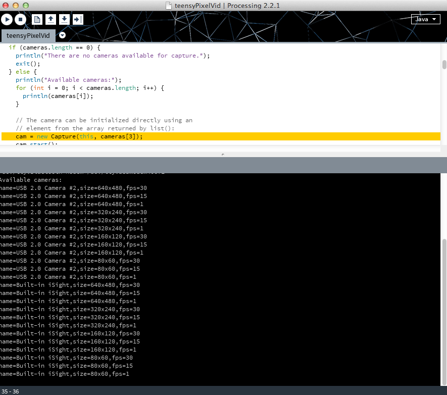
We're using the 320x240 resolution because it makes the math a little easier since we have 32 rows of LEDs. Feel free to experiment with the other settings to see what happens.
language:java
/* Live video to 32x32 RBG panel by Ben Leduc-Mills
Adapted from Benjamin Poilvé www.theelectrisquid.fr
based on the work of Markus Lipp and by Alex Medeiros
*/

import processing.serial.*;
import processing.video.*;

Capture cam;
Serial serialPort;
PImage img;
byte[] matrixbuff = new byte[4096];

void setup(){
println(Serial.list());

// Open the port you are using at the rate you want:
serialPort = new Serial(this, Serial.list()[5], 500000);
String[] cameras = Capture.list();

if (cameras.length == 0) {
  println("There are no cameras available for capture.");
  exit();
} else {
  println("Available cameras:");
for (int i = 0; i < cameras.length; i++) {
  println(cameras[i]);
}

// The camera can be initialized directly using an
// element from the array returned by list():
cam = new Capture(this, cameras[3]);
cam.start();
  }
}

void draw(){
  if (cam.available() == true) {
   cam.read();
  }
  img=cam.get(0,0,320,240);
  img.resize(32,24);
  image(img,0,0);
  update();
}

void update(){
  if (serialPort != null ) {

      serialPort.write((byte)(192)); //00001000
      serialPort.write((byte)(192)); //00100001

      int pIdx = 0;
      for (int y = 0; y < 32; y++) {
        for (int x = 0; x < 32; x++) {

          float ga = 4f;

          color c = img.get(x, y);
          int r = int(red(c));
          int g = int(green(c));
          int b = int(blue(c));

          r = (byte)(Math.pow(((float)r)/255.0,ga)*255.0);
          g = (byte)(Math.pow(((float)g)/255.0,ga)*255.0);
          b = (byte)(Math.pow(((float)b)/255.0,ga)*255.0);

          matrixbuff=drawPixel888(x,y,(byte)r,(byte)g,(byte)b,matrixbuff);
          pIdx++;
        }}

    serialPort.write(matrixbuff);
    //println(matrixbuff);
  }
}


byte[] drawPixel888(int x, int y, byte r, byte g, byte b, byte target[]) {
int rowLength = 32*8;

int targetRow =getTargetRow(y);
boolean targetHigh =  getTargetHigh(y);

int baseAddr = targetRow*rowLength;
for (int i=0; i<8; i++)
{
  int baseAddrCol = baseAddr+getTargetCol(x,i);
  int bit = 1<<i;

  target[baseAddrCol]&= targetHigh?7:56; //zero target bits

  if ((r & bit) != 0)
    target[baseAddrCol]|=targetHigh?8:1;
  if ((g & bit) != 0)
    target[baseAddrCol]|=targetHigh?16:2;
  if ((b & bit) != 0)
    target[baseAddrCol]|=targetHigh?32:4;
    }
  return target;
}

int getTargetRow(int y)
{
  return y%16;
}

int getTargetCol(int x, int bit)
{
  return x+bit*32;
}

boolean getTargetHigh(int y)
{
  return y>=16;
}
Putting it All Together
Now for the big finish! Plug in the RGB Panel power supply to a wall outlet, the Teensy 3.1 and webcam get plugged in to your computer's USB ports. Now start the Processing sketch; it will take a little bit to start up as it goes through all the available cameras (if you have a Mac you'll notice the green light on your iSight flash on and off once or twice). Once it starts up, a little preview box will pop up on your computer, and your RGB matrix should come to life, with the image from the webcam showing up (somewhat pixelated) on the RGB panel.
For photos, we set it up to look at a SparkFun flame sticker:

You may have noticed a few scraps of red cardboard on top of the sticker. Turns out the lighting in the studio and the reflectivity of the sticker (it's shiny) caused the sticker to get washed out - so we improvised.
Resources and Going Further
A lot of people have been playing around with these awesome RGB LED panels and have developed some pretty sweet tools and hacks to explore and integrate into your own experiments. Here are a few I dug up, and please suggest other resources in the comments!
- SmartMatrix Library
- OctoWS2811 Library
- Dangeous Prototypes Library
- Penguin Tech Project
- Using Raspberry Pi
- Using BeagleBone Black
That's all I've got for now - post your projects in the comments below - we'd love to check them out!