$48.50
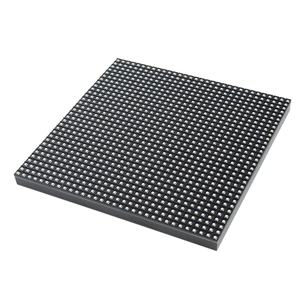
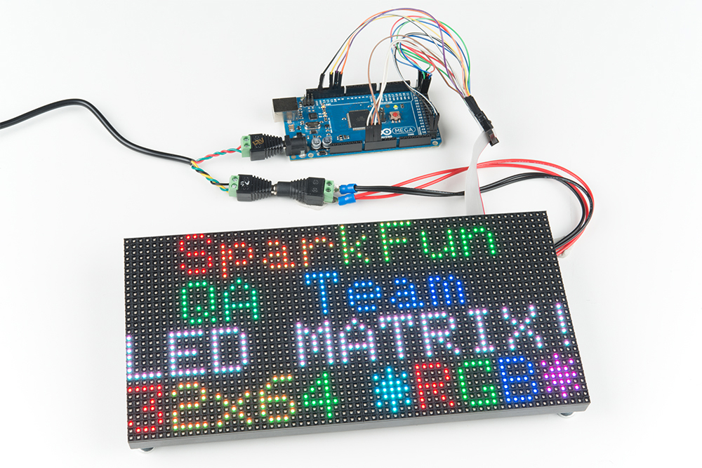
Are you looking to add a lot of color to your project? These massive RGB LED panels are an awesome place to start. You can create animations, games, or all sorts of other fun displays with them. Depending on the manufacturer, these panels can come in different sizes, LED pitch, and scan rates. Here are the ones that SparkFun currently carries in the catalog:
In this tutorial we'll show you just how, exactly, these panels operate. We'll dig into the hardware hookup and examine how to best power them. Then we'll work up a demo sketch and control them with Arduino.
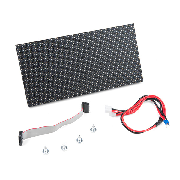
On top of either size panel, you'll also need:
Before following along with this tutorial, we recommend reading through these tutorials first:
These panels require a regulated 3.3-5V supply for power. And that supply needs to be able to source a good amount of current -- up to 2A in the worst case (all pixels bright, hot, white). For a 32x64, one of these panels was pulling about ~3.36A-3.43A without a heat sink -- so about up to 4A worst case. A 4-pin (2 for VCC, 2 for GND), 0.15"-pitch polarized connector should be used to supply power to the panel. Depending on the manufacturer, the color and location of the power connector may be different.
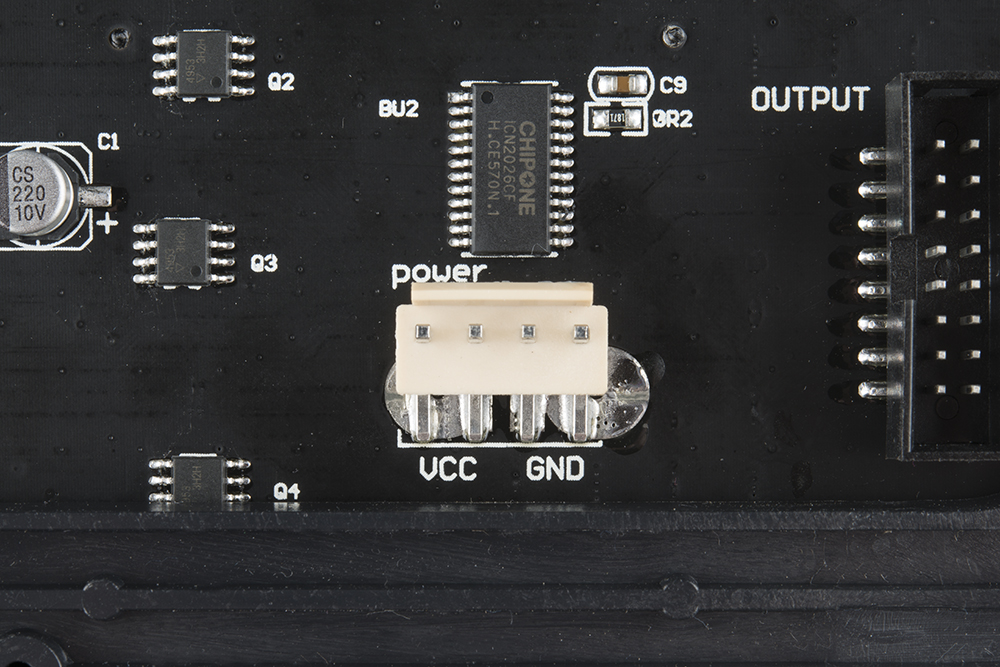
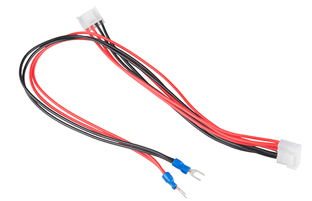
Included with the panel is a dedicated cable for power. It's a 0.15" pitch 4-pin polarized connector. The included cable is terminated with both a female polarized connector, and a pair of spade terminals.
Here are a few methods we've used to power the panel. If you are powering the Arduino with a different voltage, make sure to connect GND in order to have the same reference voltage.
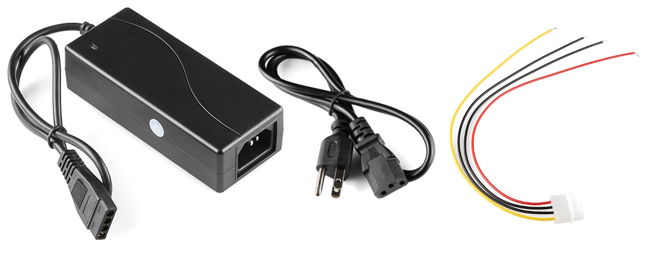
This is our recommended combo:
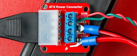
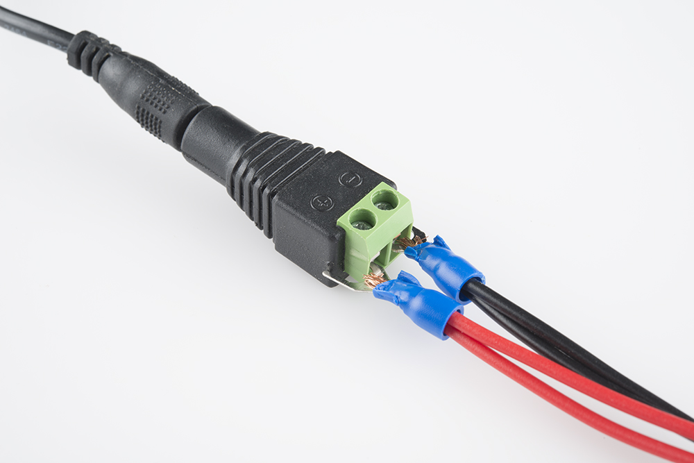
Your final connection should look similar to the closeup of the connection below with the LED panel's forked spade connector and wires inserted into the screw terminals.
You can also splice the wires using the following combinations:
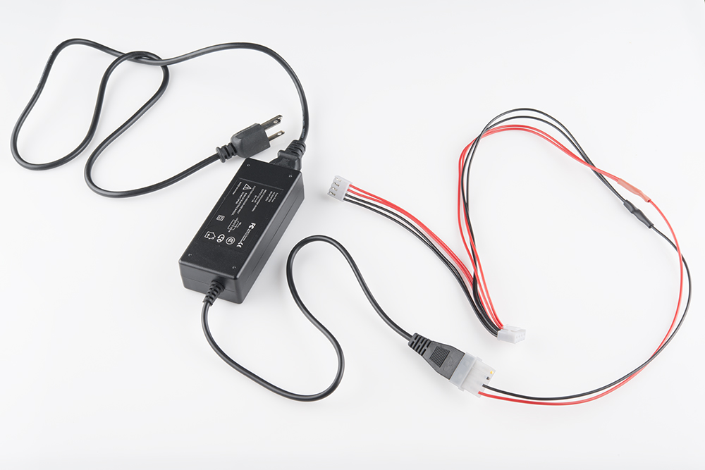
To begin, we snipped the spade connectors off of the panel power supply cable. And then stripped the newly unterminated ends.
Then we spliced the Molex pigtail to the LED panel's power cable by connecting the red wires together. Do the same for the black wires (make sure you use the black wire next to the red on the Molex pigtail). Make sure you are connecting to the 5V and GND pins and NOT the 12V pin. Before connecting to the RGB Matrix Panel, test the connection with a multimeter.
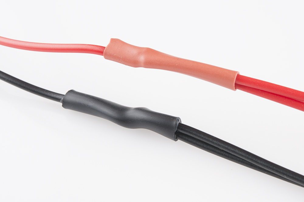
Finally, cover the splice with heat shrink or electrical tape, and voila! That's a beautiful power cable.
This is a nice, sturdy interface between the panel and a solid power supply. If you're looking for something easier, but less reliable check the below option.
For those that want to push the panels to the limit (i.e. setting the pixels on a 32x64 panel at full white at maximum capacity), combine:
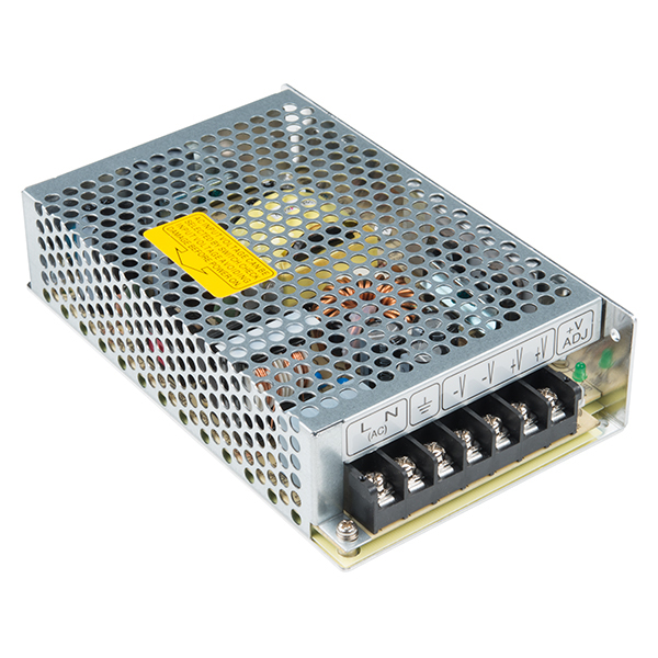
Grab a 5V wall adapter. Both been tested to work with the panels as well. At least in the short term.
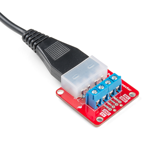
Use the power supply in conjunction with a female barrel jack adapter and screwdriver to get a quick and dirty connection between the spade and barrel jack.
The final connection should look like the image below.

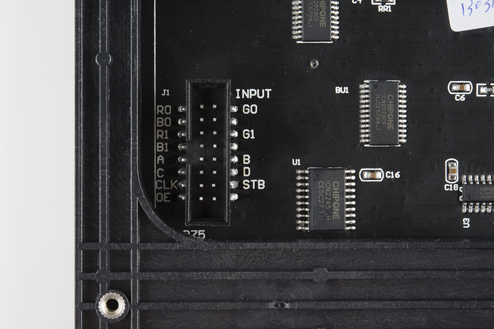
Before we can get into the code portion, there's quite a bit of wiring to do. The RGB panels have a pair of 16-pin (2x8) IDC connectors, and we need to wire up to most of those pins. Conveniently, both panels have the connector pins labeled (the unlabeled pins are ground). As we're hooking up to the panel, make sure you use the connector labeled Input. The labeling may be slightly different depending on the manufacturer.

Here are the pin connections between LED panel connector and Arduino:
| Panel Pin Label | Cable Connector Pin # | Arduino Uno (Atmega328P) Pin |
Arduino Mega 2560 Pin |
Notes |
|---|---|---|---|---|
| R0 | 1 | 2 | 24 | Red Data (columns 1-16) |
| G0 | 2 | 3 | 25 | Green Data (columns 1-16) |
| B0 | 3 | 4 | 26 | Blue Data (columns 1-16) |
| GND | 4 | GND | Ground | |
| R1 | 5 | 5 | 27 | Red Data (columns 17-32) |
| G1 | 6 | 6 | 28 | Green Data (columns 17-32) |
| B1 | 7 | 7 | 29 | Blue Data (columns 17-32) |
| GND | 8 | GND | Ground | |
| A | 9 | A0 | Demux Input A0 | |
| B | 10 | A1 | Demux Input A1 | |
| C | 11 | A2 | Demux Input A2 | |
| D | 12 | A3 | Demux Input E1, E3 (32x32 panels only) | |
| CLK | 13 | 11 | LED Drivers' Clock | |
| STB | 14 | 10 | LED Drivers' Latch | |
| OE | 15 | 9 | LED Drivers' Output Enable | |
| GND | 16 | GND | Ground | |
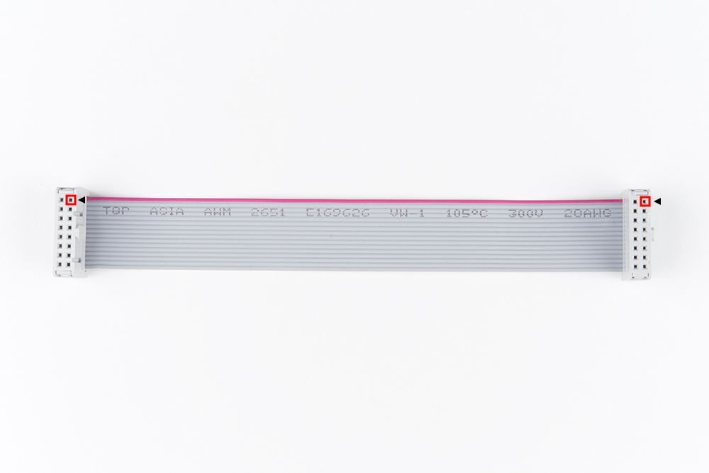
For a more step-by-step approach, follow along below. We use male-to-male premium jumper wires to wire between the included ribbon cable and our Arduino.
These LED driver (shift register) data pins are hard-coded in the Arduino library and can't be moved. As listed in the table above, R0, G0, B0, R1, G1, and B1 go to the Arduino Uno's pins 2 through 7 respectively. If you're wiring the panel up to an Arduino Mega, these pins should be connected to pins 24-29 respectively.
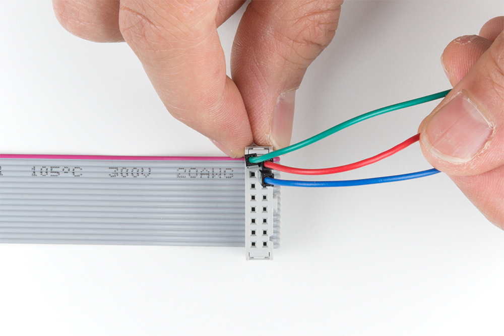
For reference when wiring the pins, try looking down at the IDC connector with red wire on top. The cable connector's pin 1 is relative to the top right. If you look really closely at the molding, you may also arrow (◄) pointing to that pin. Also, note that the tab for polarity is on the right side on either end of the cable.
Once you decide what side to connect, start wiring pin 1 by connecting a red wire for R0. Then connect pin 2 by connecting a green wire for G0. After connecting pin 3 using a blue wire for B0, continue wiring the pins based on the hookup table.
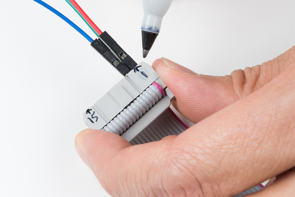
To help keep track of what side you are connecting to, feel free to label your connections with a marker.
This is the last pin that has some restriction on where it can go -- it must be connected to one of Arduino's port B pins. That means it must be either 8, 9, 10, 11, 12, or 13. The example code has it defined as pin 11 in the hookup table. Make sure to check your pin definition for the clock as it may vary with the code you are using.
These five (or six if you're using a 32x32 matrix) pins can be plugged in anywhere you may have space on your Arduino. Although, there's probably not a lot of room left... We chose to stick A, B, and C in pins A0, A1, and A2 respectively. OE connects to pin 9. STB to pin 10. And, if you're using a 32x32 matrix, D goes to A3 as stated in the hookup table.
Feel free to swap those up if your application requires. Just make sure you switch it up in the example code too.
Last, but certainly not least (well, maybe, if we're talking about potential) is ground. There are three unlabeled pins on the connector which should all be tied to ground.
If you don't have anything else plugged into them, there should be three ground pins available on your Arduino. If you're struggling to find ground pins, though, you should be able to get away with only plugging one of the ground pins to your Arduino. Woo color coded wires!
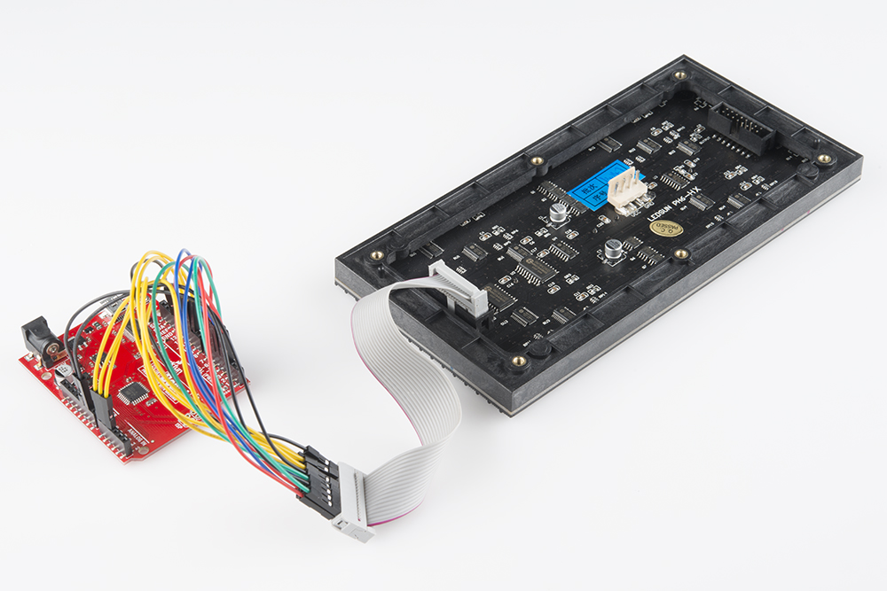
Once you are finished connecting the LED panel to an Arduino, add your 5V power supply to the panel's power connector. Don't forget to add power to your Arduino!
 |
 |
| 16x32 Fully Connected to the RedBoard | 32x32 Fully Connected to the Arduino Mega 2560 |
For anyone connecting to the 32x64 RGB Panels, you will need to use an Arduino Mega 2560 with the library. Otherwise, the panels will not be able to display as expected due to the limitations of the library and the Arduino Uno.
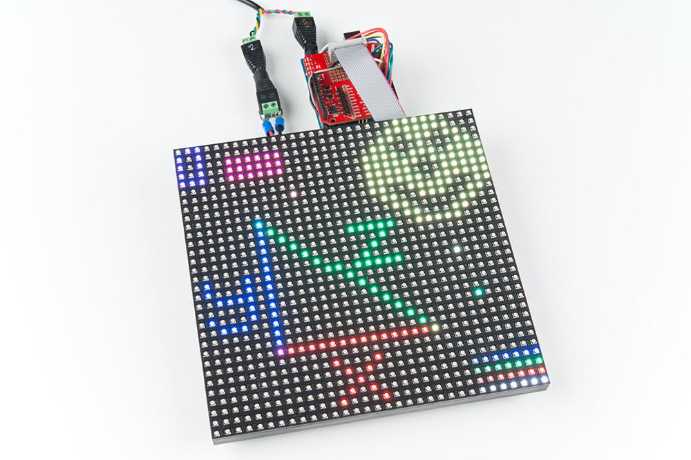
To daisy chain two 32x32 RGB matrices together, connect another IDC cable from the output of the first panel to the input of the second panel. Then connect the second 4-pin polarized connector to the input power connector. After modifying the test_shapes_32x64.ino, the display will output as a 32x64 matrix as shown below.
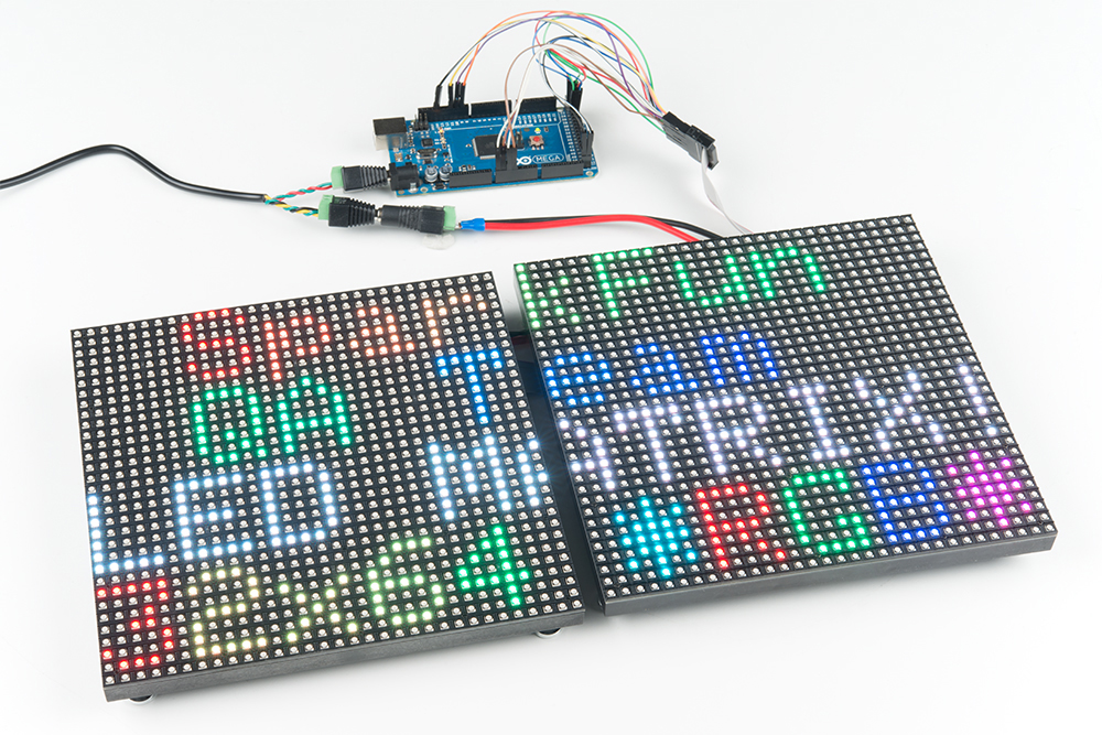
Here's an example with the 32x64 matrix with 4mm pitch.
When using an array higher than 32x64, another library would be a better option with a Teensy 3.0+, FPGA, or Raspberry Pi. You may need to level shift to convert 3.3V to 5V for the RGB LED panel to recognize the I/O signals. For more information, check out the links in the Resources and Going Further.
If you have a prototyping shield, try making a custom shield adapter for a more secure connection. Here's an example of using an XBee shield's prototyping area with the connection specifically for the RGB LED panels. Follow the steps outlined above but solder the connection together.
Depending on the supplier, you may receive a set of magnetic mounts. Add it to the panel's mounting holes to stick on a fridge or metal wall! They also work great as a standoff. Just make sure to secure and insulate your wires to prevent any shorts if there is metal behind the panel.

Note: This example assumes you are using the latest version of the Arduino IDE on your desktop. If this is your first time using Arduino, please review our tutorial on installing the Arduino IDE. If you have not previously installed an Arduino library, please check out our installation guide.
Our example code is going to make use of Adafruit's most excellent RGBMatrixPanel library, which also requires their AdafruitGFXLibrary. You can obtain these libraries through the Arduino Library Manager by searching for those names. Or you can manually install them can by grabbing both of them [RGBMatrixPanel and AdafruitGFXLibrary] from their GitHub repositories.
For your convenience, we packaged those libraries with the serial paint example code used in the tutorial:
The RGBMatrixPanel library includes a number of fun examples to help show how the library can be used. They're awesome. Check them out under the File_ > Examples > _RGBMatrixPanel menu in Arduino. (Definitely check out the Plasma_16x32 or Plasma_32x32 examples!). Make sure to adjust the code based on your hardware hookup. In this tutorial, we physically connected the clock pin to 11. Therefore, you need to adjust the defined CLK pin from
language:c
// If your 32x32 matrix has the SINGLE HEADER input,
// use this pinout:
#define CLK 8  // MUST be on PORTB! (Use pin 11 on Mega)
#define OE  9
#define LAT 10
#define A   A0
#define B   A1
#define C   A2
#define D   A3
to:
language:c
// If your 32x32 matrix has the SINGLE HEADER input,
// use this pinout:
#define CLK 11  // MUST be on PORTB! (Use pin 11 on Mega) <---CHANGE!
#define OE  9
#define LAT 10
#define A   A0
#define B   A1
#define C   A2
#define D   A3
64" as a parameter when creating an instance of the RGBmatrixPanel class:
RGBmatrixPanel matrix(A, B, C, D, CLK, LAT, OE, false, 64);
We wanted to write another fun sketch that provided an interactive way to explore with the panels and the Arduino library. What we came up with is a serial-controlled paint program. With this sketch, you can use the serial monitor (or, better yet, another terminal program) to control a cursor and draw on the matrix.
Download and unzip the sketch included in the zipped libraries using the link below if you have not already.
Before uploading, make sure the sketch is set up to work with your panel where it says:
language:c
/* - One of these should be commented out!
   - Also, make sure to adjust the saved image in the <bitmap.h> file.*/

/* ========== For 32x64 LED panels: ==========
  You MUST use an Arduino Mega2560 with 32x64 size RGB Panel */
//RGBmatrixPanel matrix(A, B, C, D, CLK, LAT, OE, false, 64); // 32x64

/* ========== For 32x32 LED panels: ========== */
RGBmatrixPanel matrix(A, B, C, D, CLK, LAT, OE, false); // 32x32

/* ==========  For 32x16 LED panels: ========== */
//RGBmatrixPanel matrix(A, B, C, CLK, LAT, OE, false); // 32x16
By default, the Serial Paint example uses the 32x32. If you are using 32x64, make sure to uncomment the following line by removing the "//"
language:c
//RGBmatrixPanel matrix(A, B, C, D, CLK, LAT, OE, false, 64); // 32x64
Then comment out the following line by adding a "//" at the beginning of the line.
language:c
RGBmatrixPanel matrix(A, B, C, D, CLK, LAT, OE, false); // 32x32
Make sure to also uncomment/comment out the bmp[] array in the bitmap.h file by removing and adding "/*" and "*/" for your respective size.
Once you have adjusted the code to your screen, upload it to the Arduino! After upload, a single pixel should be blinking at the top left of the panel. It doesn't look like much, but that's a good sign.
To control the program, open up your serial terminal to 9600 bps. Try hitting sending l (lowercase 'L') through the serial monitor, which should load the demo bitmap. You can send E (uppercase) to erase the screen.
The idea of this sketch is: move the cursor around to draw pixels, shapes, or text. Here are the commands made available by the sketch (they are case-sensitive):
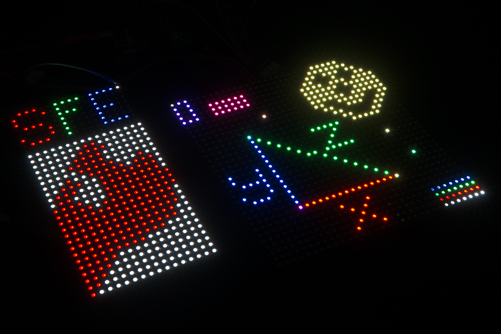
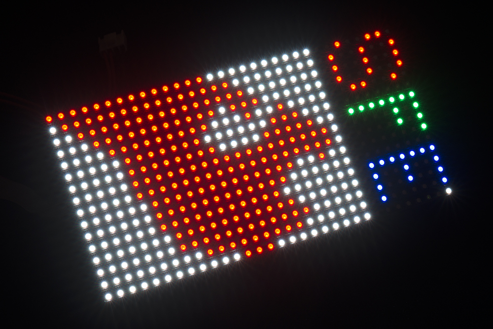
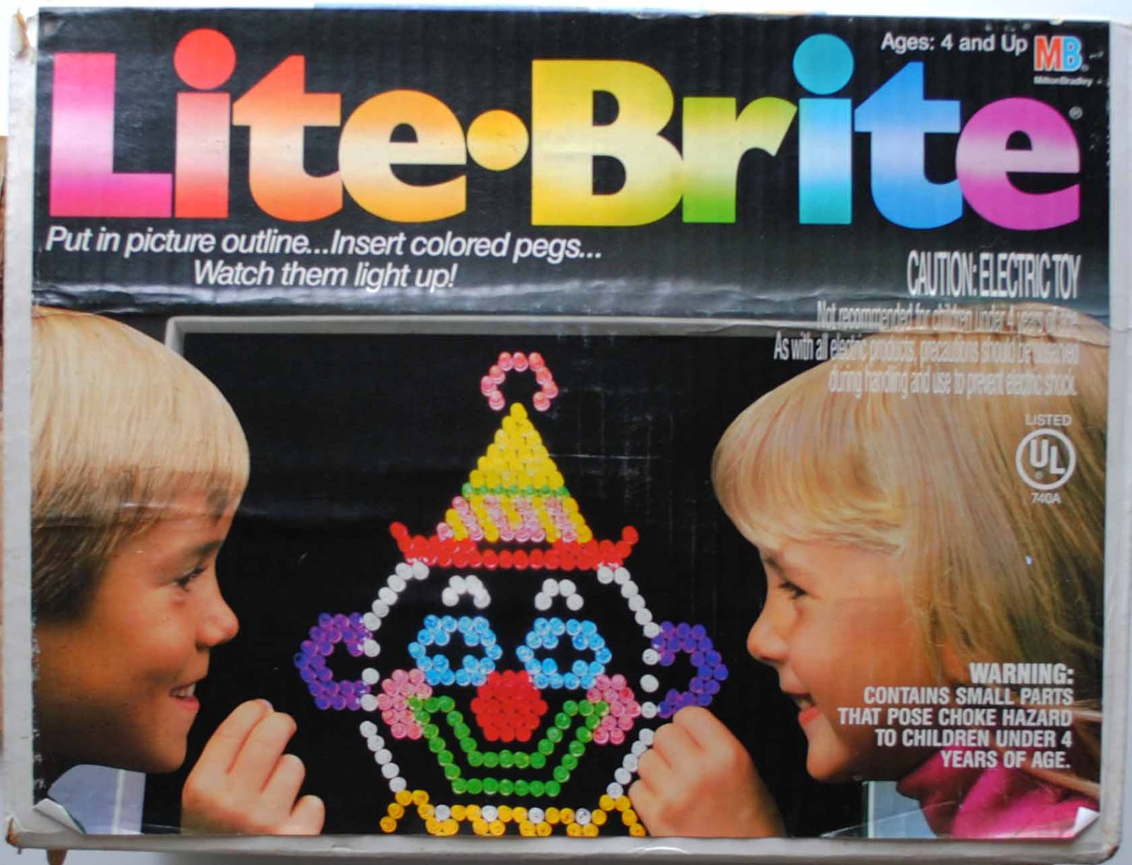
w, a, s, d (up, down, left, right)SpacebareEfR (values between 0 [off] and 7 [most bright])rG/gB/bz (copies a color under the cursor)v to place starting point. Then move cursor to endpoint and press v again.x or X to place first corner. Then move your cursor to where you want the diagonal corner. Then press either x for an empty box, or X for a filled box.c or C to place the center of the circle. Then move your cursor to where you want the outside edge of your circle to be. Then press c for an empty circle or C for a filled circle.t to go to text mode. Now any characters received will be displayed on the panel. It'll wrap around from one line to the next, but not from bottom to top. Press ` (above Tab / left of 1) to exit text mode.p to print an array of your drawing to the serial terminal. You can copy this, and put it back in your sketch if you want to load it again.l to load a pre-defined array from the sketch. The sketch includes a demo array, which was created from the print command. Follow this example to load your own drawings!Give the paint sketch a try! See if you can make the next great Lite-Brite LED Panel picture. If you make something neat, share it with us! Don't laugh. I drew that SFE flame one pixel at a time! Here are our creations:
 |
 |
| A drawing on the 16x32 panel. | An example drawing on the 32x32 panel. |
Try modifying the code to change the color and move around the matrix using potentiometers and buttons. You can see it in action in our product showcase:
Now that you know how to make use of these beautiful RGB LED matrices, what nifty project are you going to create with them? Here are some more resources, if you need them:
Looking for a faster processor and more memory to drive RGB LED matrices? Try looking at the SmarLED Shield for Teensy.
Try making a hover pong game with the 32x32 RGB LED Matrix using a gesture sensor and the SmartLED Shield. The example code can be found in the GitHub repo HoverPong.
Need some inspiration for your next project? Check out some of these related tutorials:
If you're looking for even more inspiration or more stuff to learn, check out these tutorials:
learn.sparkfun.com | CC BY-SA 3.0 | SparkFun Electronics | Niwot, Colorado