RedBoard Qwiic Hookup Guide
Arduino Examples
Example 1: Uploading Blink
In this example we will go over the basics of the Arduino IDE and upload a sample code. This is a great way to test the basic functionality of any board to make sure it is working.The Arduino IDE
Now it's finally time to open up the Arduino software. You'll be presented with a window that looks a little something like this: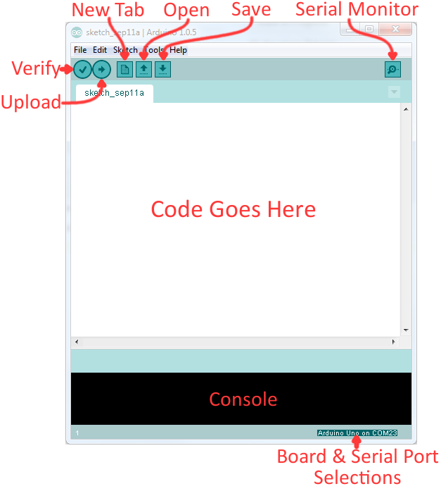
Layout of the Arduino IDE.
Before we can send the code over to the RedBoard, there are a couple of adjustments we need to make.
Select a Board
This step is required to tell the Arduino IDE which of the available Arduino boards, we are using. Go up to the Tools menu. Then hover over Board and make sure Arduino/Genuino Uno is selected.
Screen shot of Board selection.
Select a Serial Port
Next up we need to tell the Arduino IDE which of our computer's serial ports the RedBoard is connected to. For this, again go up to Tools, then hover over Serial Port and select your RedBoard's COM port.
Screen shot of COM Port selection.
If you've got more than one port, and you're not sure which of the serial ports is your RedBoard, unplug it for a moment and check the menu to see which one disappears.
Blink Sketch
Code written for the Arduino IDE are referred to as sketches. All code in Arduino is C based. Let us upload a Blink sketch to make sure our new RedBoard setup is totally functional. Go up to the File menu in Arduino, then go to Examples > 01.Basics > Blink to open it up.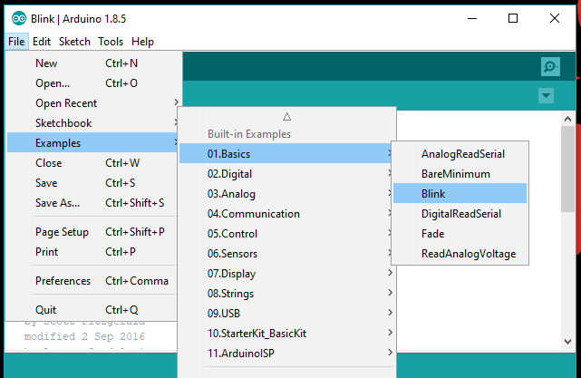
Screen shot of Blink sketch selection.
Upload!
With all of those settings adjusted, you're finally ready to upload some code! Click the Upload button (the right-pointing arrow) and allow the IDE some time to compile and upload your code. It should take around 10-20 seconds for the process to complete. When the code has uploaded, you should see something like this in your console window: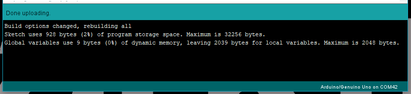
Screen shot of upload complete.
And if you look over to the RedBoard, you should see the blue LED turn on for a second, off for a second, on for a second, off for a second...ad infinitum (at least until it loses power).
Expected response from board
If you want to adjust the blink speed, try messing with the "1000" value in the
delay(1000); lines. You're well on your way to becoming an Arduino programmer!
Something Wrong?
Uh oh! If you didn't get a "Done Uploading" message, and instead got an error, there are a few things we can double-check.If you got an avrdude: stk500_getsync(): not in sync: resp=0x00 error in your console window.
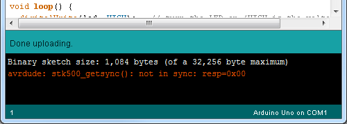
Screen shot of Error Message in the Console.
Either your serial port or board may be incorrectly set. Again, make sure Arduino/Genuino Uno is the board selection (under the "Tools > Board" menu). The serial port is usually the more common culprit here. Is the Serial Port correctly set (under the "Tools > Serial Port" menu)? Did the drivers successfully install? To double check your RedBoard's serial port, look at the menu when the board is plugged in, then unplug it and look for the missing port. If none of the ports are missing, you may need to go back to driver installation.
Example 2: Qwiic Connector
One of the great features of the RedBoard (Qwiic) is its ability to interface with I2C devices using our Qwiic system. The Qwiic system is a solderless connection system that allows users to seamlessly daisy chain multiple I2C devices with ease.The Qwiic Distance Sensor
For this example, we will be running a basic sketch using the SparkFun 4m Distance Sensor (VL53L1X). For more examples with this sensor, please refer to the complete hookup guide.Hardware Assembly
The wiring for this is simple. Use the Qwiic cable and connect the distance sensor to the board. That is it! The connections are polarized, so you don't have to worry about which side or connector you are using.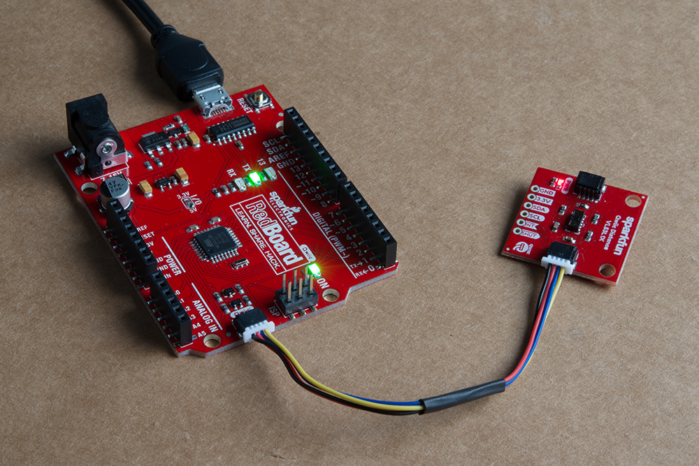
Let's run an example for our distance sensor to see how it behaves.
Install the Arduino Library
Note: If you have not previously installed an Arduino library, please check out our Arduino library installation guide.
First, you'll need the Sparkfun VL53L1X Arduino library. You can obtain these libraries through the Arduino Library Manager. Search for Sparkfun VL53L1X Arduino Library to install the latest version. If you prefer downloading the libraries from the GitHub repository and manually installing it, you can grab them here:
Example 1 - Read Distance
To get started with this example, open up File > Examples > SparkFun VL53L1x 4M Laser Distance Sensor > Example1_ReadDistance. In this example, we begin by creating aSFEVL53L1X object called distanceSensor with our wire port, Wire, and then our shutdown and interrupt pins. Then we initialize our sensor object in the setup() loop. The code to do this is shown below.
language:c
#include <Wire.h>
#include "SparkFun_VL53L1X.h"

//Optional interrupt and shutdown pins.
#define SHUTDOWN_PIN 2
#define INTERRUPT_PIN 3

SFEVL53L1X distanceSensor(Wire, SHUTDOWN_PIN, INTERRUPT_PIN);

void setup(void)
{
  Wire.begin();

  Serial.begin(9600);
  Serial.println("VL53L1X Qwiic Test");

  if (distanceSensor.init() == false)
    Serial.println("Sensor online!");

}
Once we've initialized our sensor, we can start grabbing measurements from it. To do this, we send some configuration bytes to our sensor using distanceSensor.startRanging() to initiate the measurement. We then wait for data to become available and when it does, we read it in, convert it from millimeters to feet, and print it out over serial. The void loop() function that does this is shown below.
language:c
void loop(void)
{
  distanceSensor.startRanging(); //Write configuration bytes to initiate measurement
  int distance = distanceSensor.getDistance(); //Get the result of the measurement from the sensor
  distanceSensor.stopRanging();

  Serial.print("Distance(mm): ");
  Serial.print(distance);

  float distanceInches = distance * 0.0393701;
  float distanceFeet = distanceInches / 12.0;

  Serial.print("\tDistance(ft): ");
  Serial.print(distanceFeet, 2);

  Serial.println();
}
Opening your serial monitor to a baud rate of 9600 should show the distance between the sensor and the object it's pointed at in both millimeters and feet. The output should look something like the below image.
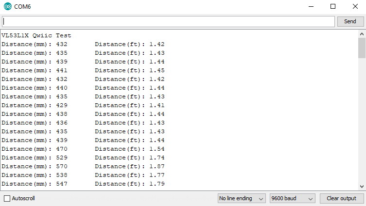
Distance readings in mm and ft