RED-V Development Guide
 bboyho,
  Englandsaurus
Examples (Freedom Studio)
Example: Hello World!
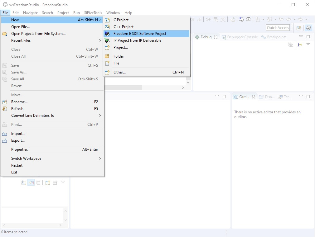
Once everything is unzipped, you'll simply need to run 'FreedomStudio.exe' to install the application. Upon opening Freedom Studio, we'll want to create a new project from one of our example templates. To do this, go to File > New > Freedom E SDK Software Project.
SparkFun's RED-V RedBoard and Thing Plus are very similar to to SiFive's HiFive1 RevB, so we'll be selecting the HiFive1 Rev B (sifive-hifive-revb) as our target board selection.
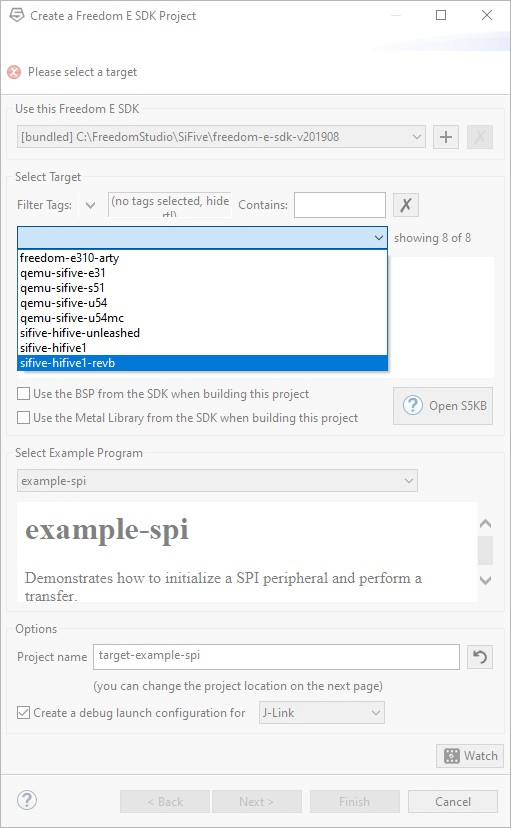
To start, let's keep it simple by flashing the "Hello World" example to our RED-V and see some serial output.
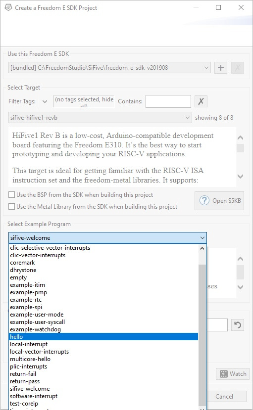
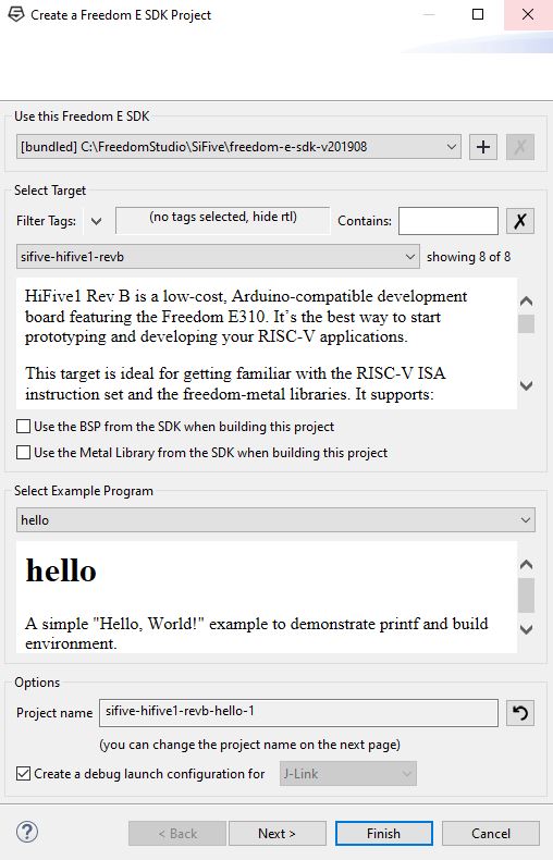
Select hello from the drop down menu. Hit Finish to load the example. You'll need to wait a little as the example project builds.
Run
After the sketch builds, a window will open to edit the debug configuration. For now, click on the Close button. Now that the example is built, hit the run button to upload and execute the code on the RED-V. If you have more than one project saved, simply click on the drop down menu next to the run button to select the project to compile and run.

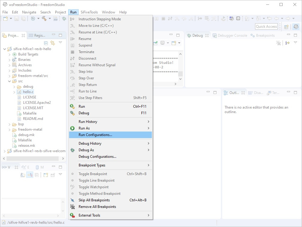
Freedom Studio will then attempt to flash and run the sketch. However, your GDB server might be configured incorrectly to be able to flash code through Freedom Studio. To fix this, go to Run -> Run Configurations... from the menu.
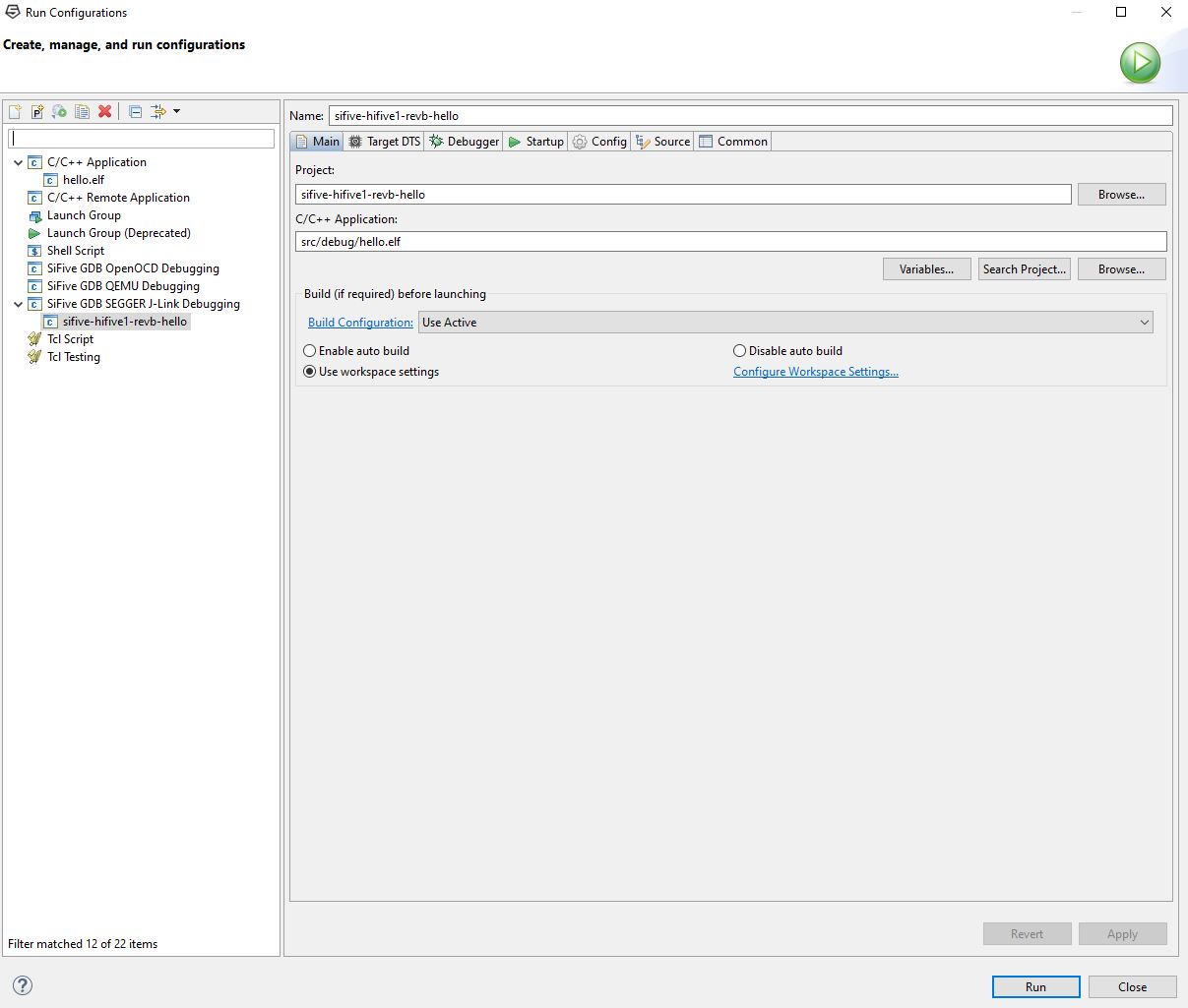
Open the SiFive GDB SEGGER J-Link Debugging tree on the left hand side of the window, select your project, and hit the Run button. This will flash the code over USB and begin running your code as well.
Drag and Drop
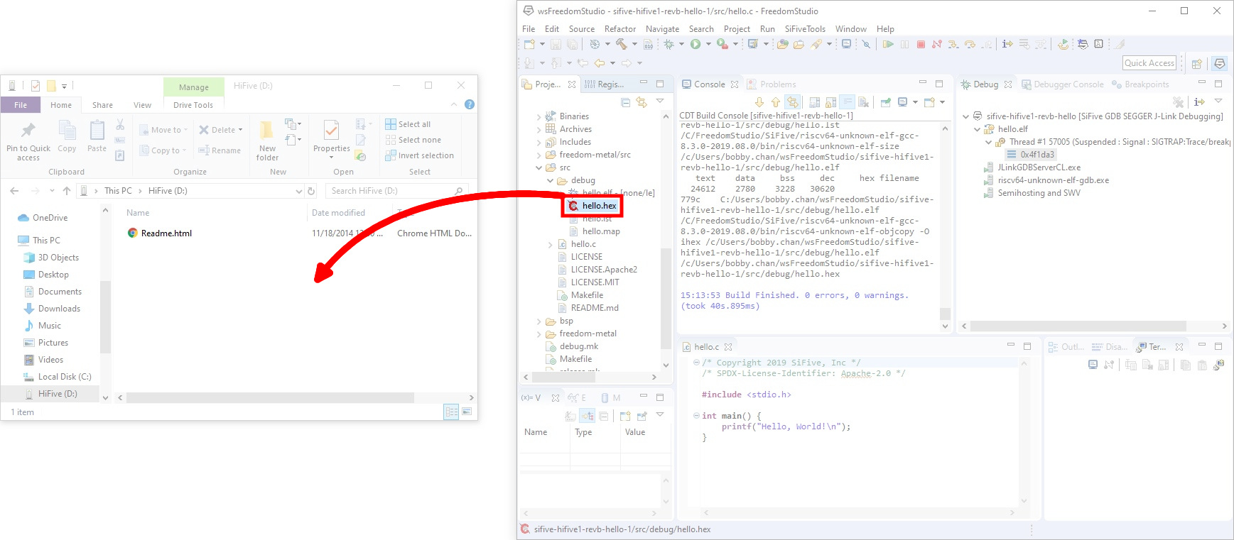
Another way to flash is using the shortcut CTRL+B to build all the files; this will generate a *.hex file in the Project Explorer under src -> debug -> hello.hex .

You may have noticed that the RED-V shows up as a flash drive when you plug it into your computer. With the window for the drive opened, drag and drop the *.hex directly onto this drive to program the RED-V.
What You Should See
The program will begin running once the code has been uploaded to the RED-V RedBoard. To see the serial output, you'll need a serial terminal. While you could connect using your favorite serial terminal, we'll use the one built into the Freedom Studio. In the Freedom Studio software, you'll notice a window on the bottom right of the software. Click on the tab labeled as Terminal and then the icon with the monitor.
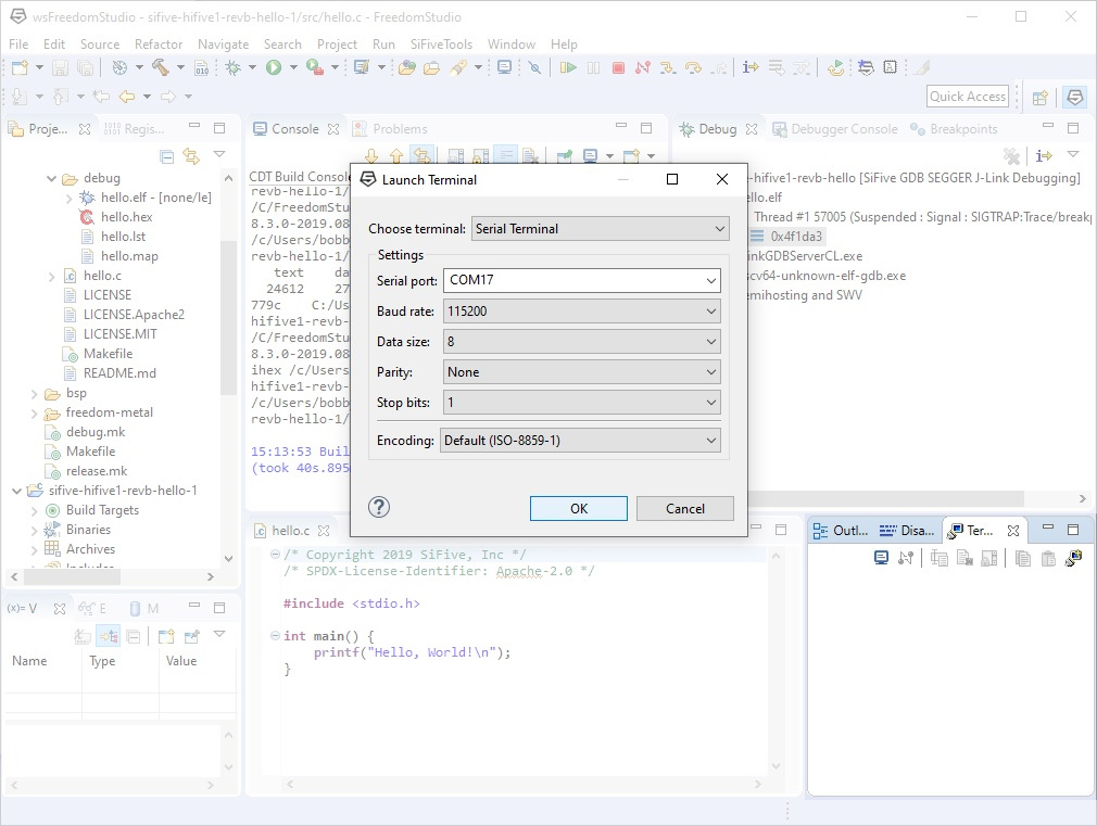
A new window will pop up asking for you to choose your serial terminal and the settings. Click on the Choose terminal: menu and select Serial Terminal. The board will show up as two COM ports on your computer: one for the bootloader and another one for the example program. Most likely the COM port will show up as the one with the second to highest number. The default baud rate of the example projects are set to 115200 baud (8 data bits, no parity, 1 stop bit, default encoding). With the correct settings, hit the OK button to connect. The example code will print "Hello World!" once so we'll need to hit the reset button on the board one time.
You'll some serial output as the RED-V boots up. Once it enters the example program, the RED-V RedBoard will output the familiar message that all programmers know and love: "Hello, World!"
language:bash
Bench Clock Reset Complete

ATE0--> Send Flag error: #255 #255 #255 #255 AT+BLEINIT=0--> Send Flag error: #255 #255 #255 #255 AT+CWMODE=0--> Send Flag error: #255 #255 #255 #255
Hello, World!

Example: Blink
0. In order to properly use a pin as an output, make sure to also follow the sequence to disable and enable the I/O pin in the code.
Now that we have output some serial to a terminal window, let's try to blink the LED on the RED-V. Let's just use the example project that we have open already in Freedom Studio. Copy and paste the example below into the text editor.
language:c
/******************************************************************************
    RED-V_blink.c

    WRITTEN BY: Ho Yun "Bobby" Chan and "Tron Monroe"
    @ SparkFun Electronics
    DATE:  11/21/2019

    DEVELOPMENT ENVIRONMENT SPECIFICS:
      Firmware developed using Freedom Studio v4.12.0.2019-08-2
      on Windows 10

    ========== RESOURCES ==========
    Freedom E SDK

    ========== DESCRIPTION ==========
    Using the built-in LED. To test with different pin,
    simply modify the reference pin and connect a standard LED
    and 100?O resistor between the respective pin and GND.

    LICENSE: This code is released under the MIT License (http://opensource.org/licenses/MIT)
  ******************************************************************************/


#include <stdio.h>      //include Serial Library
#include <time.h>       //include Time library
#include <metal/gpio.h> //include GPIO library, https://sifive.github.io/freedom-metal-docs/apiref/gpio.html

//custom write delay function since we do not have one like an Arduino
void delay(int number_of_microseconds){ //not actually number of seconds

// Converting time into multiples of a hundred nS
int hundred_ns = 10 * number_of_microseconds;

// Storing start time
clock_t start_time = clock();

// looping till required time is not achieved
while (clock() < start_time + hundred_ns);

}

int main (void) {
  printf("RED-V Example: Blink\n");

  struct metal_gpio *led0; //make instance of GPIO

  //Note: The sequence of these commands matter!

  //Get gpio device handle, i.e.) define IC pin here where IC's GPIO = 5, pin silkscreen = 13
  //this is the GPIO device index that is referenced from 0, make sure to check the schematic
  led0 = metal_gpio_get_device(0);

  // quick check to see if we set the metal_gpio up correctly, this was based on the "sifive-welcome.c" example code
  if (led0 == NULL) {
    printf("LED is null.\n");
    return 1;
  }
  //Pins are set when initialized so we must disable it when we use it as an input/output
  metal_gpio_disable_input(led0, 5);

  //Set as gpio as output
  metal_gpio_enable_output(led0, 5);

  //Pins have more than one function, make sure we disconnect anything connected...
  metal_gpio_disable_pinmux(led0, 5);

  //Turn ON pin
  metal_gpio_set_pin(led0, 5, 1);


  while (1) {//loop through, sort of like an Arduino loop()

      //Turn OFF pin
      metal_gpio_set_pin(led0, 5, 0);
      //Use custom "delay" function
      delay(2000000); //2000000 "micro-seconds" ~ 1 second, through experimentation...
      //Turn ON pin
      metal_gpio_set_pin(led0, 5, 1);
      //Use custom "delay" function
      delay(2000000);

  }

  // return
  return 0;
}
When ready, hit the run button to compile and upload. You can also compile and drag the *.hex into the drive.
What You Should See
There'll be an output on the terminal window indicating that we are using the blink code. What we are more interested in is if the LED is turning on and off. Check your board and you should see the built-in LED begin to blink about once a second! Make sure to check out the comments in the example code. Toggling the LED is not as intuitive and straight forward as controlling an LED on an Arduino.