Raspberry Pi 2 Starter Kit Hookup Guide
This Tutorial is Retired!
This tutorial covers concepts or technologies that are no longer current. It's still here for you to read and enjoy, but may not be as useful as our newest tutorials.
View the updated tutorial: Raspberry Pi 3 Starter Kit Hookup Guide
 MTaylor
 Assembly
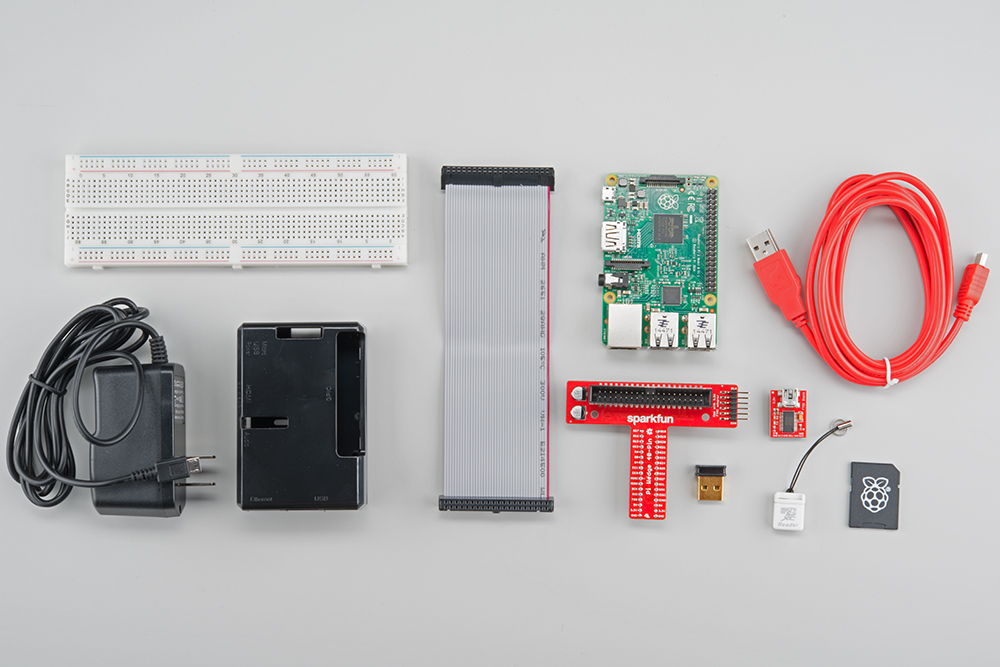
The Pi is pretty straight-forward and easy to put together, but, in the event that something doesn't look right, this section will give you an idea of what it is supposed to look like.
Snap the pi into the base of the 'tin', snap on the top part
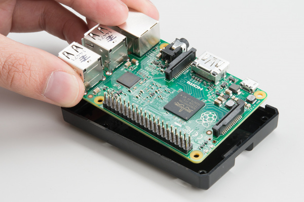
Fit the Pi into the base of the tin
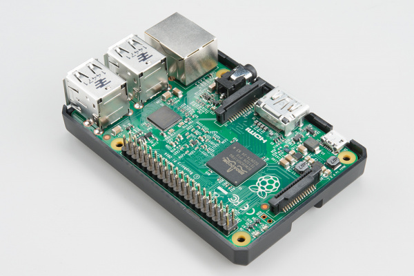
Make sure the Pi is fully seated. Check that the PCB is evenly recessed about the perimeter.
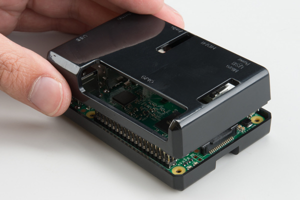
Click the two halves together<//center>
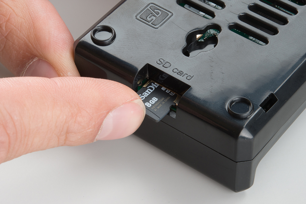
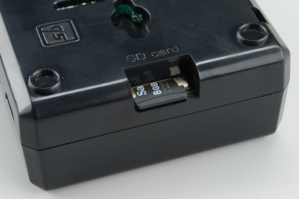
Add the SD card

Installing an SD card -- make sure the "cliky pen" action of the card is in the depressed position prior to adding power

The microSD card should be flush with the side of the case when inserted properly.
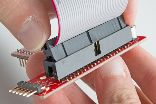
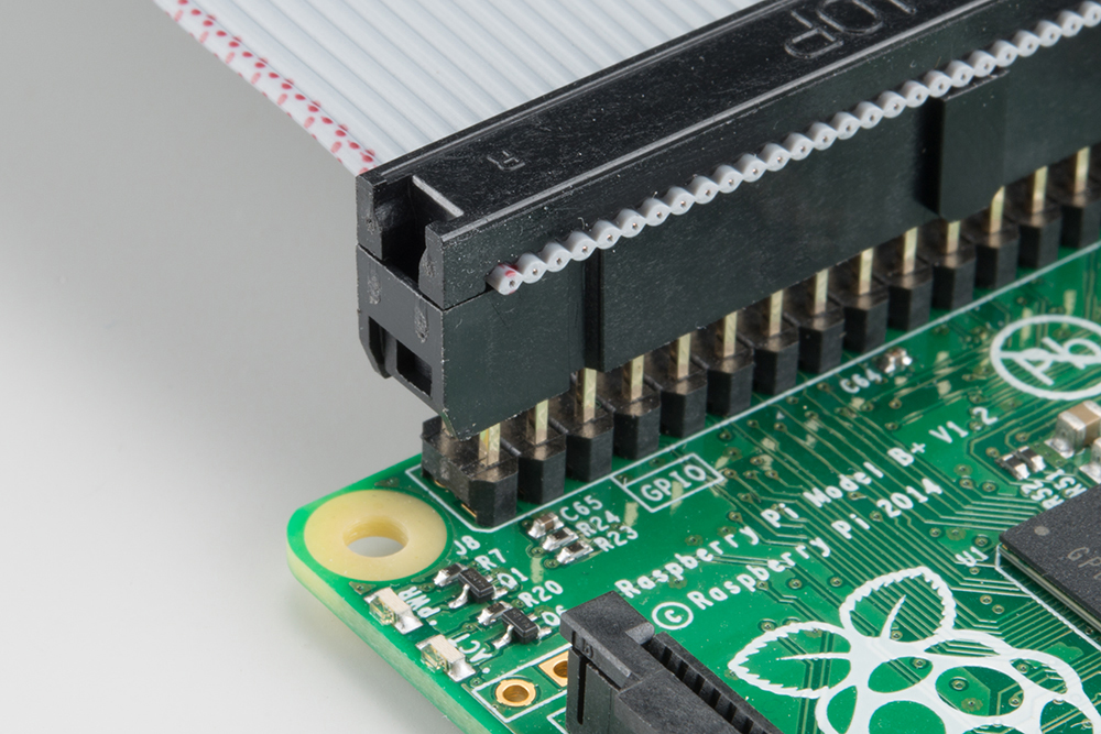
Connect the ribbon cable to the Pi -- notice that the pin 1 marking is very subtle. Orient the red stripe on the cable towards the SD card. Alternately, pin 1 can be identified by finding the missing/beveled corner of the header's silkscreen, on the pi.

The pin 1 location and silkscreen is the same between the Pi B+ ad Pi B. This image shows a partially inserted ribbon cable without the case in the way.

*The ribbon cable is orinted with the red "pin 1" marking towards the SD card slot *
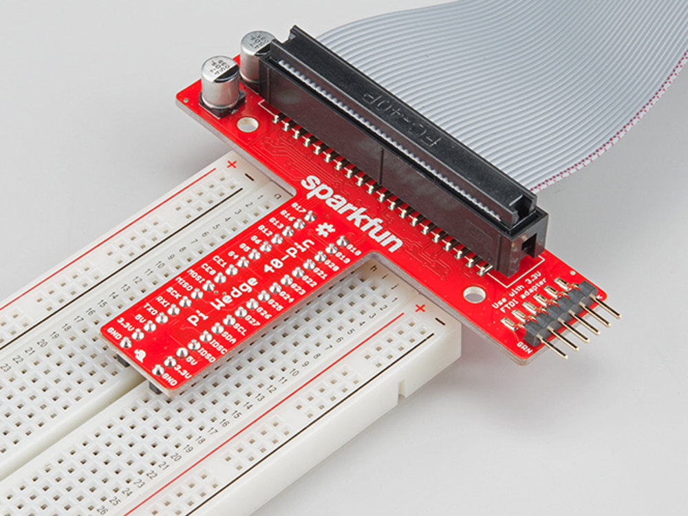
Attach the ribbon cable to the wedge. Pin 1 is towards the FTDI adapter
Socket the end of the ribbon cable into the Wedge. It is keyed, but each end of the cable is different. Make sure the ribbon extends away from the breadboard connection.
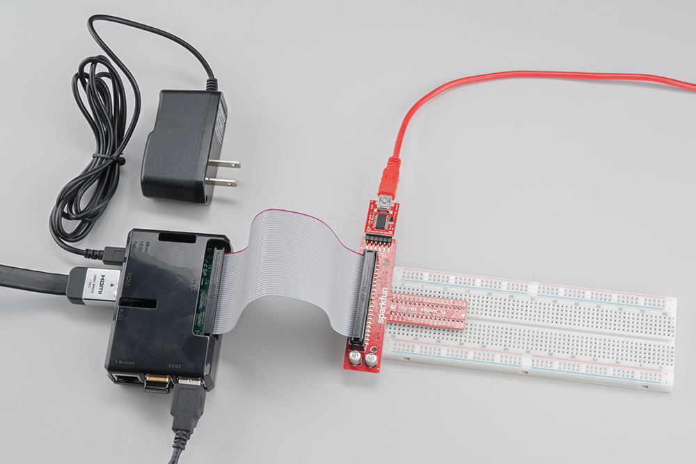
Socket the wedge into your breadboard

Wedge inserted in breadboard.
Attach the FTDI connector matching "GRN" to "GRN" between the boards
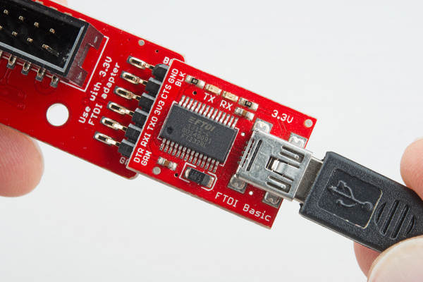
The FTDI serial adapter is connected matching GRN and BLK connections
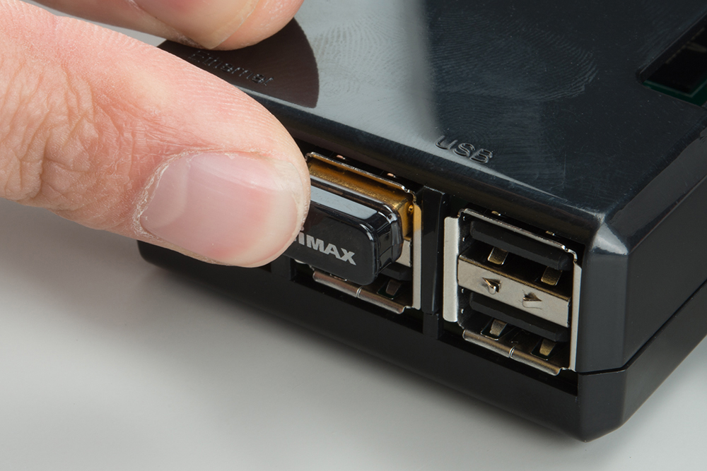
Add the Edimax WiFi dongle, any USB

Inserting the Edimax wireless dongle. In this picture, the Edimax is fully seated.
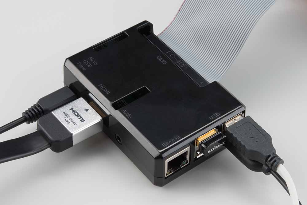
Attach desired consumer computer equipment

The fully assembled kit. Additional to the kit, user supplied monitor, mouse, and keyboard are shown. This Pi is now a desktop computer.


