Qwiic VR IMU (BNO080) Hookup Guide
 Englandsaurus
Hardware Overview
Let's look over a few characteristics of the BNO080 sensor so we know a bit more about how it behaves.
| Characteristic | Range |
|---|---|
| Operating Voltage | 1.65V - 3.6V |
| Linear Acceleration Accuracy | ±.35m/s2 |
| Gyroscope Accuracy | ±.35m/s2 |
| I2C Address | 0x4B (S0 Pulled High) or 0x4A (S0 grounded) |
Pins
There are multiple rows of pins on the BNO080, the first row, used for the default I2C interface (configurable up to 400 kHz) is explained in the table below.
| Pin Label | Pin Function | Input/Output | Notes |
|---|---|---|---|
| PS0 | Protocol Selection | Input | Configuration of the communication interface (Default: 0, I2C) |
| PS1 | Protocol Selection | Input | Configuration of the communication interface (Default: 0, I2C) |
| GND | Ground | Input | 0V/common voltage. |
| 3V3 | Power Supply | Input | Should be between 1.65 - 3.6V |
| SDA | I2C Data Signal | Bi-directional | Bi-directional data line. Voltage should not exceed power supply (e.g. 3.3V). |
| SCL | I2C Clock Signal | Input | Clock signal. Voltage should not exceed power supply (e.g. 3.3V). |
| RST | Reset Signal | Input | Reset signal, active low, pull low to reset IC |
| INT | Interrupt | Output | Interrupt, active low, pulls low when the BNO080 is ready for communication. |
Also broken out on the board is a Serial Peripheral Interface (SPI) which can run data up to 3MHz. The pins for this interface are outlined below. On any pin, the voltage should not exceed that supplied on the 3V3 pin.
| Pin Label | Pin Function | Input/Output | Notes |
|---|---|---|---|
| GND | Ground | Input | 0V/Common Voltage |
| 3V3 | Power | Input | Should be between 1.65 - 3.6V |
| SCK | Clock | Input | Clock signal to synchronize controller and peripheral. |
| SO | CIPO | Output | Controller in, peripheral out. Device sends data to the controller on this line. |
| SI | COPI/ADDR | Input | Controller out, peripheral in. Device receives data from the microcontroller on this line. Tie to 3.3V to change I2C address from 0x4A to 0x4B |
| CS | Chip Select | Input | Chip select, active low, used as chip select on SPI |
| WAK | Wake | Input | Active low, Used to wake the processor from a sleep mode. |
| RST | Reset Signal | Input | Reset signal, active low, pull low to reset IC |
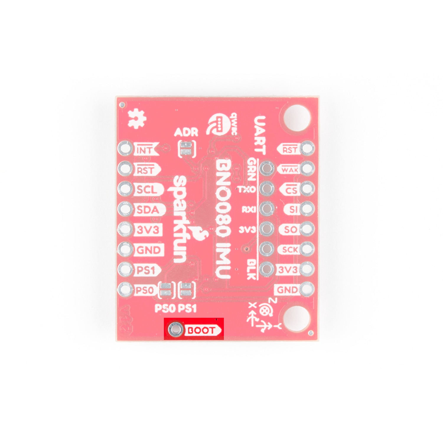
You can also use the UART interface at up to 3 Mbps or a simplified UART called UART-RVC (Used for robotic vacuum cleaners) which can run at a data rate of 115200 kbps. The UART interface is in the middle of the board, with the black and green pins labeled on the back of the board as shown below. These serial pins have been arranged to work with our Serial Basic board to make interfacing to a computer simple and fast. The GRN and BLK labels help align the serial connection properly.
Also note the BOOT pin next to the Qwiic connector, which is necessary for configuration of the communication mode. If the BOOT pin is low upon reset or power up, the chip will go into bootloader mode to allow for programming of new firmware.
Optional Features
Pull-Up Resistor Jumper
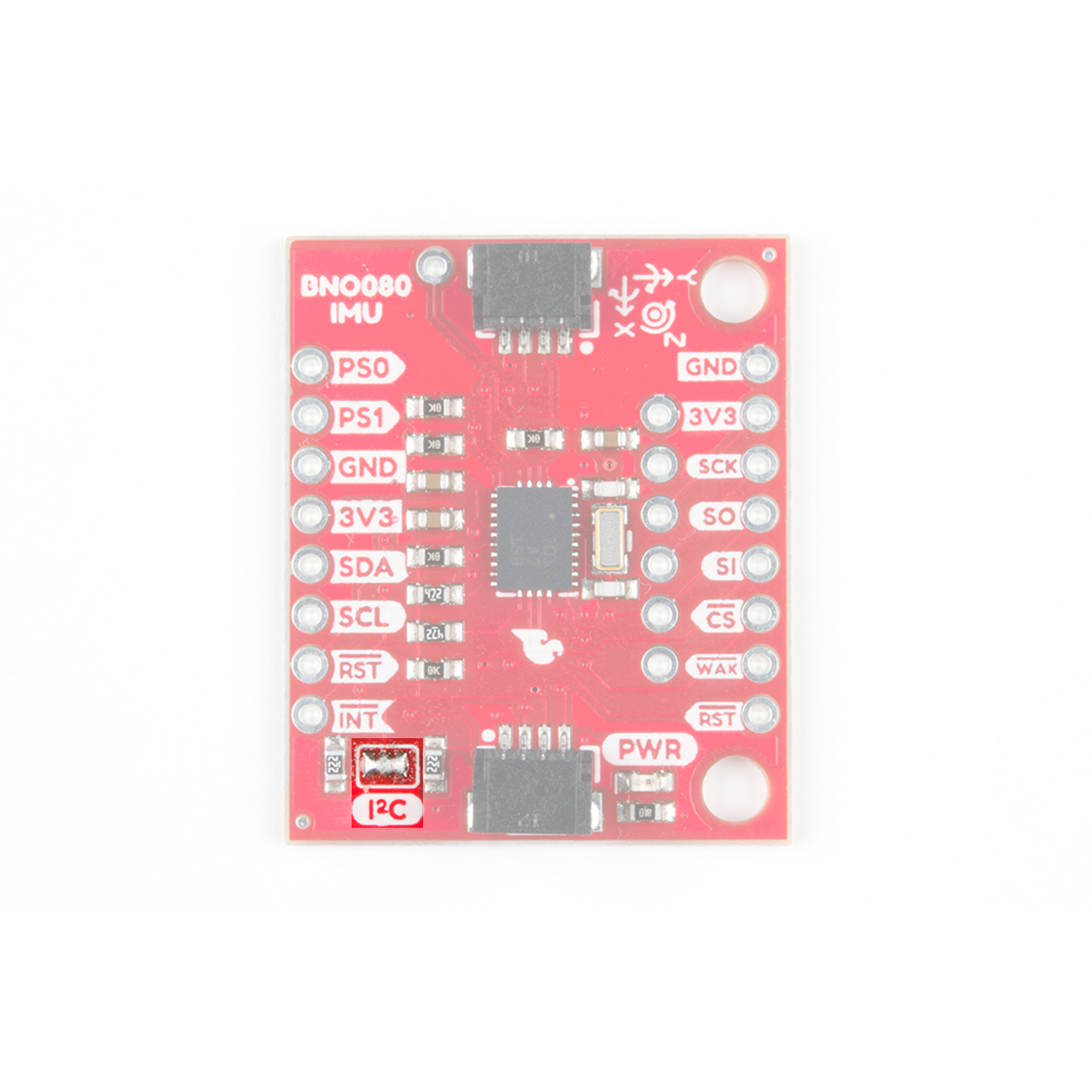
The Qwiic VR IMU has onboard I2C pull up resistors; if multiple sensors are connected to the bus with the pull-up resistors enabled, the parallel equivalent resistance will create too strong of a pull-up for the bus to operate correctly. As a general rule of thumb, disable all but one pair of pull-up resistors if multiple devices are connected to the bus. If you need to disconnect the pull up resistors they can be removed by removing the solder on the corresponding jumpers highlighted below.
Protocol Selection Jumpers
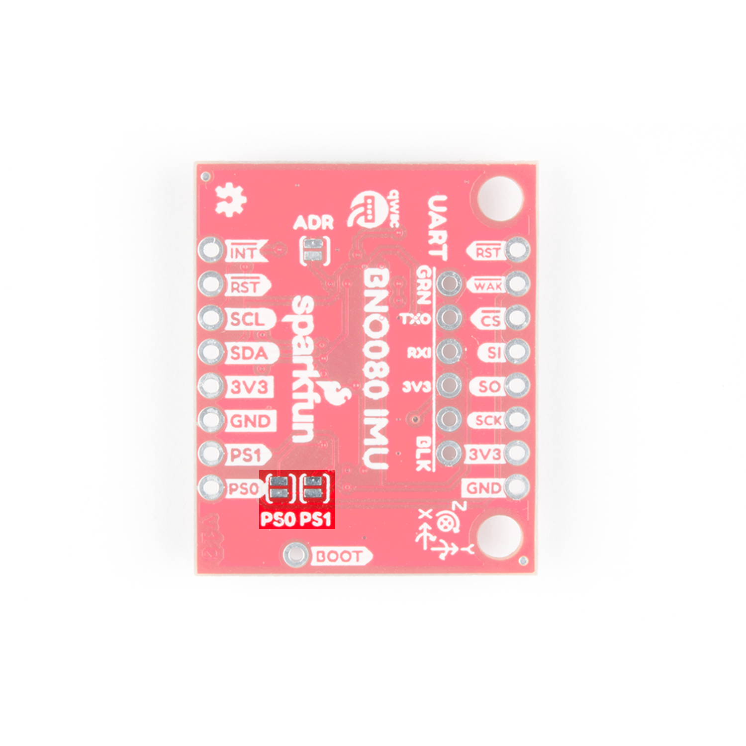
You can use the PS0 and PS1 jumpers to change the communication protocol that the BNO080 is using. The jumpers are left open (0) by default, and the following configurations will allow for their corresponding communications protocols.
| PS0 | PS1 | Interface |
|---|---|---|
| 0 | 0 | I2C |
| 1 | 0 | UART-RVC |
| 0 | 1 | UART |
| 1 | 1 | SPI |
The jumpers themselves are located on the back of the board, shown below
I2C Jumper
You can also change the address of the BNO080 from 0x4B (default) to 0x4A by connecting the I2C ADR jumper. The jumper itself is shown in the below image.

Axis Reference
Also, be sure to check out the labeling on the front of the board that indicates the orientation of the positive X, Y, and Z axes so you know which way your data is pointing.
