Qwiic VR IMU (BNO080) Hookup Guide
 Englandsaurus
Arduino Example Code
Now that we have our library installed, we can get started playing around with our examples to learn more about how the IMU behaves. From there we'll be able to build our own custom code to integrate the sensor into a project.
Example 1 - Rotation Vector
This first example gets us started taking a reading of our complex valued rotation vector, or quaternion, which tells us how we are oriented. To get started, open up Example1-RotationVector under File > Examples > SparkFun BNO080 Cortex Based IMU > Example1-RotationVector. To access all of the functions in the BNO080 library we'll have to include the library and create an IMU object, this is accomplished in the following lines of code.
language:c
#include "SparkFun_BNO080_Arduino_Library.h"
BNO080 myIMU;
In our setup(), we'll have to initialize the sensor and enable the parts of the sensor (gyro, accelerometer, magnetometer) that we want to obtain readings from. We'll also tell the IMU how often we want a reading from our sensor of choice by passing this value into our enable function in ms. The code outlining this sensor setup is shown below. Pay attention to this as we'll be performing a similar setup in many of the remaining examples.
language:c
Serial.begin(9600); //Don't forget to enable Serial to talk to your microcontroller
Serial.println();
Serial.println("BNO080 Read Example");

Wire.begin(); //Begin the I2C bus
Wire.setClock(400000); //Increase I2C data rate to 400kHz

myIMU.begin();
myIMU.enableRotationVector(50); //Send data update every 50ms
Now that our sensor is setup, we can look at our void loop() to see how we obtain and print data. When the loop executes, it begins by checking to see if the sensor has new data with myIMU.dataAvailable(), which returns true when new data is available. We then proceed to get the i, j, k, and real quaternion values along with the accuracy in radians of our measurement using the following lines of code.
language:c
float quatI = myIMU.getQuatI();
float quatJ = myIMU.getQuatJ();
float quatK = myIMU.getQuatK();
float quatReal = myIMU.getQuatReal();
float quatRadianAccuracy = myIMU.getQuatRadianAccuracy();
Printing the rotation vector is then as easy as using a few Serial.print(quatI, 2) statements. Uploading the code and opening the Serial Monitor to a baud rate of 9600 should yield an output similar to the below image.

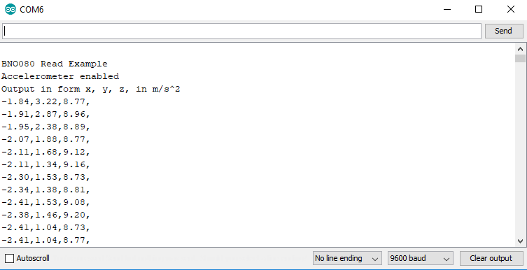
Example 2 - Accelerometer
Examples 2 deals with pulling the accelerometer values from our sensor to figure out how it is moving. To get started, open up Example2-Accelerometer under File > Examples > SparkFun BNO080 Cortex Based IMU > Example2-Accelerometer. At first glance, you'll notice that the way we set up our IMU is nearly identical to the first example. The one difference being in our setup(), where we call myIMU.enableAccelerometer(50); instead of myIMU.enableRotationVector(50); which has the accelerometer report a value every 50 ms. We once again obtain and output our data in our void loop() by waiting for data using myIMU.dataAvailable(). Once data is available we use the following lines of code to get our x, y, and z acceleration values.
language:c
float x = myIMU.getAccelX();
float y = myIMU.getAccelY();
float z = myIMU.getAccelZ();
We can then print these values to get our acceleration vector, uploading the code, and opening the Serial Monitor to a baud rate of 9600 should yield an output similar to the below image.
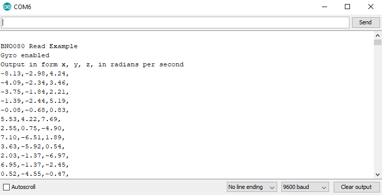
Example 3 - Gyro
In example 3, we'll pull values from the IMU's gyroscope to get a vector for our angular velocity. To get started, open up Example3-Gyro under File > Examples > SparkFun BNO080 Cortex Based IMU > Example3-Gyro. The differences between this example and example 1 are very similar to the differences between examples 1 & 2. We initialize the sensor the exact same way as example 1 only calling myIMU.enableGyro(50); instead of myIMU.enableRotationVector(50); to have the gyro report it's value every 50 ms. We once again obtain and output our data in our void loop() by waiting for data using myIMU.dataAvailable(). Once data is available, we use the following lines of code to get our x, y, and z gyroscope values.
language:c
float x = myIMU.getGyroX();
float y = myIMU.getGyroY();
float z = myIMU.getGyroZ();
We can then print these values to get our gyroscope angular velocity vector, uploading the code, and opening the Serial Monitor to a baud rate of 9600 should yield an output similar to the below image.
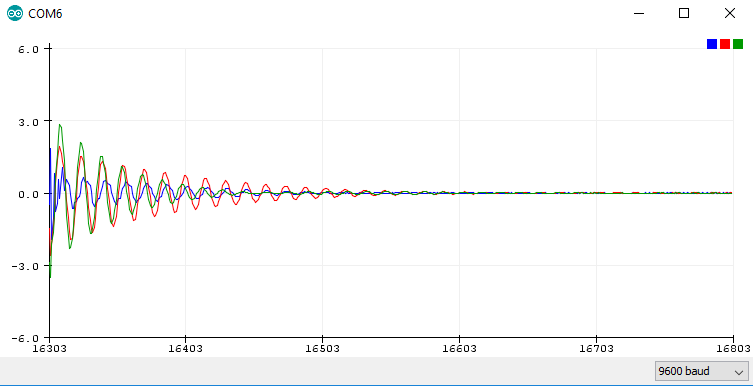
Also, check out the values in a graph by opening the Serial Plotter to the same baud rate to see the readings from each gyroscope channel plotted against each other. Rotate the IMU and see how the values respond, I got the following output just letting the IMU swing on its cable.
Example 4 - Magnetometer
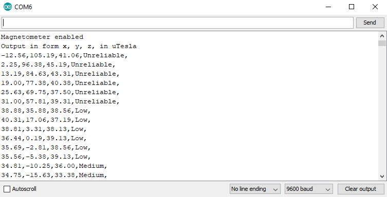
The following example will get us reading a vector for the magnetic field. To get started, open up Example4-Magnetometer under File > Examples > SparkFun BNO080 Cortex Based IMU > Example4-Magnetometer. The differences between this example and example 1 are very similar to the differences between examples 1 & 2, are you starting to see a pattern here? We initialize the sensor the exact same way as example 1 only calling myIMU.enableMagnetometer(50); instead of myIMU.enableRotationVector(50); to have the magnetometer report it's value every 50 ms. We once again obtain and output our data in our void loop() by waiting for data using myIMU.dataAvailable(). Once data is available we use the following lines of code to get our x, y, and z magnetometer values. We also obtain the uncertainty in the magnetometer.
language:c
float x = myIMU.getMagX();
float y = myIMU.getMagY();
float z = myIMU.getMagZ();
byte accuracy = myIMU.getMagAccuracy();
We can then print these values to get our magnetometer vector, uploading the code, and opening the Serial Monitor to a baud rate of 9600 should yield an output similar to the below image.
Example 5 - Step Counter
The BNO080 has some really neat built in features due to its built in Cortex. One of these is a built in step counter. To get started with this pedometer, open up Example5-StepCounter under File > Examples > SparkFun BNO080 Cortex Based IMU > Example5-StepCounter. The differences between this example and example 1 are very similar to the differences in the previous examples. We initialize our step counter function with a lower sample rate than our previous functions as we don't expect steps to happen at as high of a rate. Due to this, we call myIMU.enableStepCounter(500) to allow for a half a second in between reports. We once again obtain and output our data in our void loop() by waiting for data using myIMU.dataAvailable(). Once data is available, we pull the amount of steps from the IMU using unsigned int steps = myIMU.getStepCount() to initialize and populate an unsigned int with the step count. We then print this value to our serial monitor. Uploading the code and opening the Serial Monitor to a baud rate of 9600 should yield an output similar to the below image.

Example 6 - Metadata
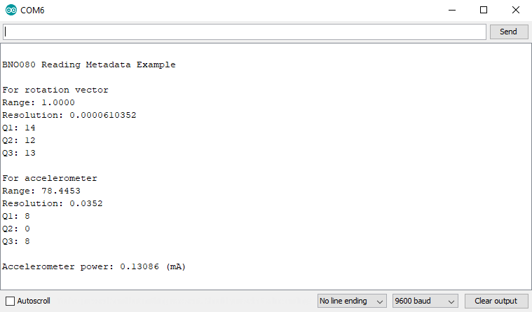
This example shows us how to retrieve the static metadata from the different sensors in the IMU. To get started, open up Example6-Metadata under File > Examples > SparkFun BNO080 Cortex Based IMU > Example6-Metadata. Notice how this example has an empty void loop()? Everything just happens once in our setup() loop. To get the metadata for a sensor, we simply pass its corresponding FRS_RECORD_ID into getRange(), getResolution(), getQ1(), getQ2(), and getQ3() to retrieve the metadata for a sensor. The different FRS_RECORD_ID variables are shown below.
language:c
#define FRS_RECORDID_ACCELEROMETER 0xE302
#define FRS_RECORDID_GYROSCOPE_CALIBRATED 0xE306
#define FRS_RECORDID_MAGNETIC_FIELD_CALIBRATED 0xE309
#define FRS_RECORDID_ROTATION_VECTOR 0xE30B
These are then used like so to print the different parts of each sensors metadata. For a little bit more on metadata, check out page 29 of the Reference Manual. Uploading the code and opening the Serial Monitor to a baud rate of 9600 should yield an output similar to the below image.
Example 7 - Stability Classifier
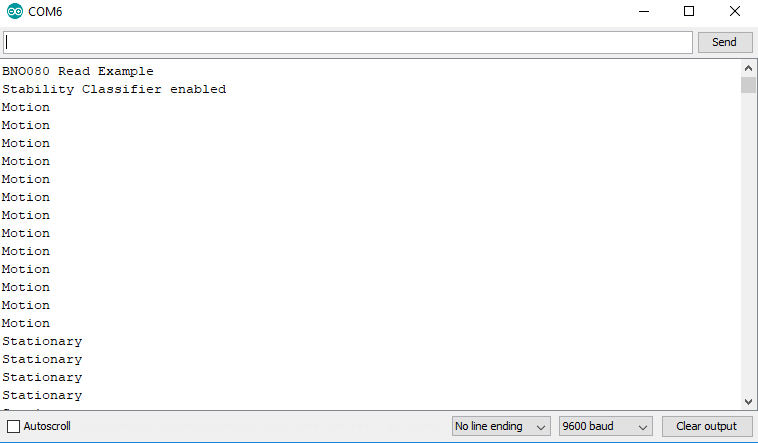
This example sketch allows us to use the built in stability classifier to figure out how stable the IMU is. To get started, open up Example7-StabilityClassifier under File > Examples > SparkFun BNO080 Cortex Based IMU > Example7-StabilityClassifier. This example is very similar to our first few examples in that we must call myIMU.enableStabilityClassifier(50); in our setup() function to have the stability classifier report its data every 50 ms. However, we also need to call myIMU.calibrateGyro() in our setup() function to enable all of our stability classification outputs. We then check if data is available using myIMU.dataAvailable(). If it is, we pull the stability classification (a number from 0-5 using myIMU.getStabilityClassifier() ) and output the text corresponding to the classification. The code that does this in the void loop() is shown below. Also, take note of which number corresponds to which activity.
language:c
if (myIMU.dataAvailable() == true)
  {
    byte classification = myIMU.getStabilityClassifier();

    if(classification == 0) Serial.print(F("Unknown classification"));
    else if(classification == 1) Serial.print(F("On table"));
    else if(classification == 2) Serial.print(F("Stationary"));
    else if(classification == 3) Serial.print(F("Stable"));
    else if(classification == 4) Serial.print(F("Motion"));
    else if(classification == 5) Serial.print(F("[Reserved]"));

    Serial.println();
  }
Uploading the code and opening the Serial Monitor to a baud rate of 9600 should yield an output similar to the below image.
Example 8 - Activity Classifier
The activity classifier is somewhat similar to the stability classifier in that it uses the on-board cortex to determine what activity the IMU is doing. To get started, open up Example8-ActivityClassifier under File > Examples > SparkFun BNO080 Cortex Based IMU > Example8-ActivityClassifier. To set up the activity classifier, we need to tell the IMU which activities to look for. We do this using a 32-bit word. There are only 8 possible activities at the moment, so we set our word enableActivities = 0x1F to enable everything. The activity classifier also gives a confidence level in each activity. To store these confidences, we create a variable byte activityConfidences[9] above our setup() function. Then, we can set up the activity classifier in our setup() function by calling myIMU.enableActivityClassifier(50, enableActivities, activityConfidences);. Using this function enables the activity classifier with 50 ms between reports, activities specified by enableActivities, and their confidences are stored in activityConfidences. We then check if data is available using myIMU.dataAvailable(). If it is, we pull the activity classification (a number from 0-9 using myIMU.getActivityClassifier()) and output the text corresponding to the classification. The code that does this is shown below. Take note of which number corresponds to which activity.
language:c
void loop()
{
  //Look for reports from the IMU
  if (myIMU.dataAvailable() == true)
  {
    //getActivityClassifier will modify our activityConfidences array
    //It will return the most likely activity as well.
    byte mostLikelyActivity = myIMU.getActivityClassifier();

    Serial.print("Most likely activity: ");
    printActivityName(mostLikelyActivity);
    Serial.println();

    Serial.println("Confidence levels:");
    for(int x = 0 ; x < 9 ; x++)
    {
      printActivityName(x);
      Serial.print(F(") "));
      Serial.print(activityConfidences[x]);
      Serial.print(F("%"));
      Serial.println();
    }

    Serial.println();
  }
}

//Given a number between 0 and 8, print the name of the activity
//See page 73 of reference manual for activity list
void printActivityName(byte activityNumber)
{
  if(activityNumber == 0) Serial.print("Unknown");
  else if(activityNumber == 1) Serial.print("In vehicle");
  else if(activityNumber == 2) Serial.print("On bicycle");
  else if(activityNumber == 3) Serial.print("On foot");
  else if(activityNumber == 4) Serial.print("Still");
  else if(activityNumber == 5) Serial.print("Tilting");
  else if(activityNumber == 6) Serial.print("Walking");
  else if(activityNumber == 7) Serial.print("Running");
  else if(activityNumber == 8) Serial.print("On stairs");
}
The output of this code should look something like the below image.

Example 9 - Calibrate
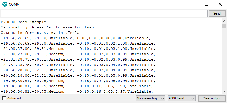
When moving between different magnetic environments (different rooms, indoors, outdoors, etc...), it might be necessary to recalibrate your IMU to obtain the best readings. In order to do this, we'll run a calibration function,. To get started, open up Example9-Calibrate under File > Examples > SparkFun BNO080 Cortex Based IMU > Example9-Calibrate. In our setup function, we call the function myIMU.calibrateAll() to begin calibration of our sensor. We also need to make sure the we enable our game rotation vector and magnetometer as these are necessary for calculating the calibration of the magnetometer. Go ahead and upload the code to the IMU and open the serial monitor to 9600 baud. Take a look at your output and look for the calibration status. This should probably say Unreliable. Make sure you're in a clean magnetic environment and go through the calibration steps listed in the calibration procedure. Once your sensor is calibrated, your accuracy should change from Unreliable to Medium or High. After calibration, send an s to your microcontroller over the serial monitor to run the following code and save the calibration.
language:c
if(incoming == 's')
{
  myIMU.saveCalibration(); //Saves the current dynamic calibration data (DCD) to memory
  myIMU.endCalibration(); //Turns off all calibration
  Serial.println("Calibration ended");
  }
}
Your Serial Monitor should look something like the following image when the sensor is being calibrated. Remember, when your confidence levels are satisfactory, send an s to save the calibration.
Example 10 - Print Packet
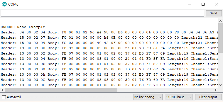
Sometimes it's easier to look at the raw data coming from the sensor for debugging purposes. This example shows you how to do just that. To get started, open up Example10-PrintPacket under File > Examples > SparkFun BNO080 Cortex Based IMU > Example10-PrintPacket. In our setup, we set up the sensors that we would like to use (in this case, we'll set up the magnetometer and accelerometer with 1000 ms sample rates). Since we're most likely debugging in this mode, we'll also call myIMU.enableDebugging(Serial). Our void loop() then simply listens for and prints packets using the below code.
language:c
void loop()
{
  //Look for reports from the IMU
  if (myIMU.receivePacket() == true)
  {
    myIMU.printPacket();
  }
}
Your Serial Monitor should look something like the following image with this example code uploaded. Make sure to change the baud rate to 115200 as opposed to 9600 like the previous examples.
Example 11 - Advanced Configuration
The final example simply shows us how to configure the sensor on different addresses and I2C buses. To get started, open up Example11-AdvancedConfig under File > Examples > SparkFun BNO080 Cortex Based IMU > Example11-AdvancedConfig. This is simply a matter of setting up the sensor differently. Instead of calling myIMU.begin() with no arguments, we call it as myIMU.begin(0x4A, Wire1). If we've pulled the SI pin high, the address will be 0x4B. We can also set up the sensor on a different I2C bus if by passing in Wire2 in place of Wire1.
Bonus Example - Serial Cube Visualizer
Note: Processing is a software that enables visual representation of data, among other things. If you've never dealt with Processing before, we recommend you also check out the Arduino to Processing tutorial. Follow the below button to go ahead and download and install Processing.
This extra example isn't included in the library as it requires Processing. To grab it, go ahead and download or clone the BNO080 Github Repo.
Processing listens for serial data, so we'll need to get our Arduino producing serial data that makes sense to Processing. The required Arduino sketch is located in Qwiic_IMU_BNO080 > Software > Serial_Cube_Rotate > Serial_Cube_Rotate.ino. This sketch simply prints a list of our quaternions separated by a comma over serial for Processing to listen to.
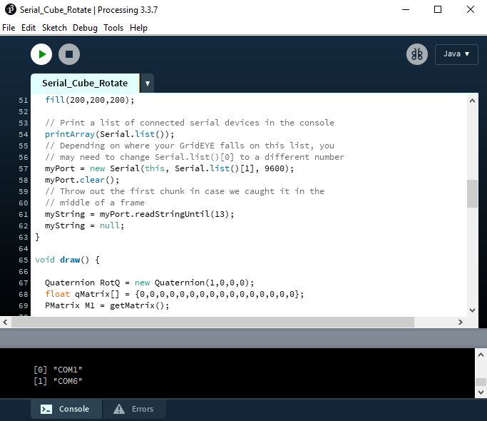
Once this sketch is uploaded, we need to tell Processing how to turn this data into a visualization. The Processing sketch to do this is located one folder above the Arduino sketch, in Qwiic_IMU_BNO080 > Software > Serial_Cube_Rotate.pde. Open the Serial_Cube_Rotate file in Processing. Before running the sketch, we'll need to download ToxicLibs, a library used for computational design. To do this, go to Sketch > Import Library... > Add Library.... Then search for and download ToxicLibs. Attempting to run the Processing sketch will show us available serial ports in the debug window from this line of code.
language:c
myPort = new Serial(this, Serial.list()[0], 115200);
Identify which serial port your Arduino is on. For instance, my RedBoard is on COM6, which corresponds to [1] in the image below, so I will need to change 0 to 1 in the following line to ensure Processing is listening to the correct serial port.
Once we've done this, we should be able to run the Processing sketch and it will give us a nice visualization of how our IMU is oriented in 3D space as a cube. Try rotating the IMU to see how it responds. You should get a neat little output like the one in the below GIF.