Qwiic MP3 Trigger Hookup Guide
 Nate
Nate Introduction
Sometimes you just need to play an MP3 file. Whether it's a sound track as you enter the room or a pirate cackling when a dollar gets donated to the kid's museum. The Qwiic MP3 Trigger takes care of all the necessary bits, all you need to do is send a simple I2C command and listen.
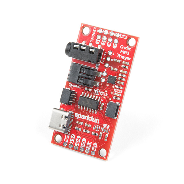
SparkFun Qwiic MP3 Trigger
DEV-19030Required Materials
The Qwiic MP3 Trigger does need a few additional items for you to get started, shown below. However, you may already have a few of these items, so feel free to modify your cart as necessary.

Suggested Reading
If you’re unfamiliar with switches, jumper pads, or I2C be sure to checkout some of these foundational tutorials.
Logic Levels
Button and Switch Basics
I2C
How to Work with Jumper Pads and PCB Traces
The Qwiic Keypad utilizes the Qwiic connect system. We recommend familiarizing yourself with the Logic Levels and I2C tutorials (above) before using it. Click on the banner above to learn more about our Qwiic products.
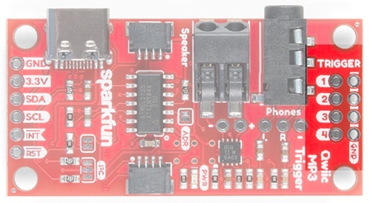
Hardware Overview
Electrical Characteristics
The Qwiic MP3 Trigger is designed to operate at 3.3V and must not be powered above 3.6V as this is the maximum operating voltage of microSD cards. The 5V power from the USB C connector tied to a robust AP2112 3.3V voltage regulator that can source up to 600mA for the board. Otherwise, the board can also be powered through the Qwiic connector.
Maximum Operating Voltages
All I/O pins are 5V tolerant but the board must but powered at 3.3V.
Recommended Operating Voltages
All I/O pins are designed to function at 3.3V. The board consumes 35mA at 3.3V in standby and can consume over 400mA when driving at 8 Ohm speaker at max volume.
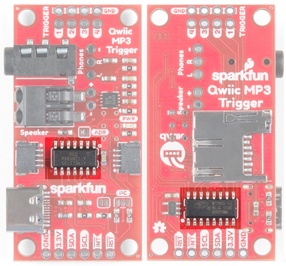
MP3 and ATtiny84
At the heart of the Qwiic MP3 Trigger is the WT2003S MP3 decoder IC. This IC reads MP3s from the microSD card and will automatically mount the SD card as a jump drive if USB is detected. The ATtiny84A receives I2C commands and controls the MP3 decoder.
SD and USB
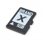
The SparkFun Qwiic MP3 Trigger works with 512MB to 32GB cards formatted in FAT32. We recommend the SparkFun 1GB MicroSD Card because it’s a good mix of low-cost and good performance for MP3 playing. Up to 255 songs can be loaded onto Qwiic MP3 Trigger.
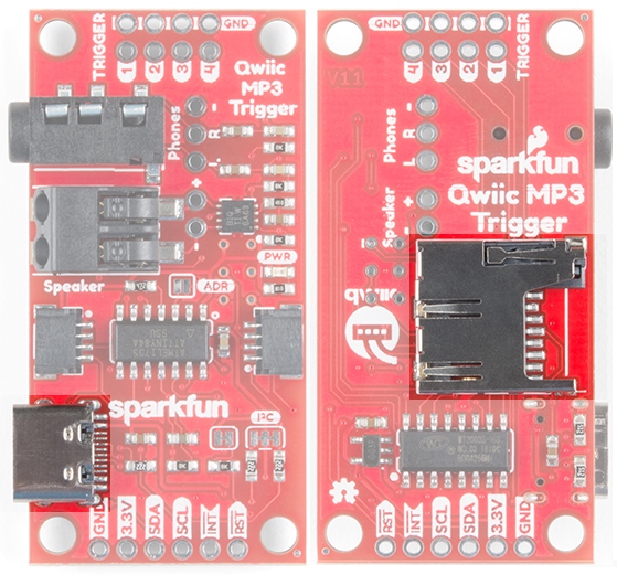
The easiest way to add and remove MP3s to the Qwiic MP3 Trigger is to attach a USB C cable. This will enumerate the microSD card as a jump drive making it extremely easy to access the files on the card. Alternatively, if you don’t want to use USB, you can eject the microSD card and read/write to it using a normal USB SD adapter.
Qwiic Connectors
The Qwiic MP3 Trigger from SparkFun includes two Qwiic connectors to make daisy chaining this music player with a large variety of I2C devices. Checkout Qwiic for your next project.
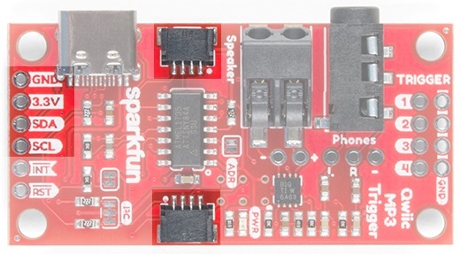
The I2C pins broken out on the board are tied directly to the Qwiic connectors.
Audio Amplifier
The speaker is boosted by a Class-D mono amplifier capable of outputting up to 1.4W. What does 1.4W mean? It's incredibly loud; great for making sure your mech effects are heard on the *con floor (i.e. _Comic_ - con, _Def_ - con, etc.) and wonderful for annoying your officemates. Both outputs have volume controlled by the SET_VOLUME command and is selectable between 32 levels. Additionally, there are PTH holes beside both connectors if a soldered connection is preferred.

0x07 command (see Command Set section). The volume setting is saved to NVM (non-volatile memory) and loaded at power on.
Audio Outputs
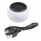
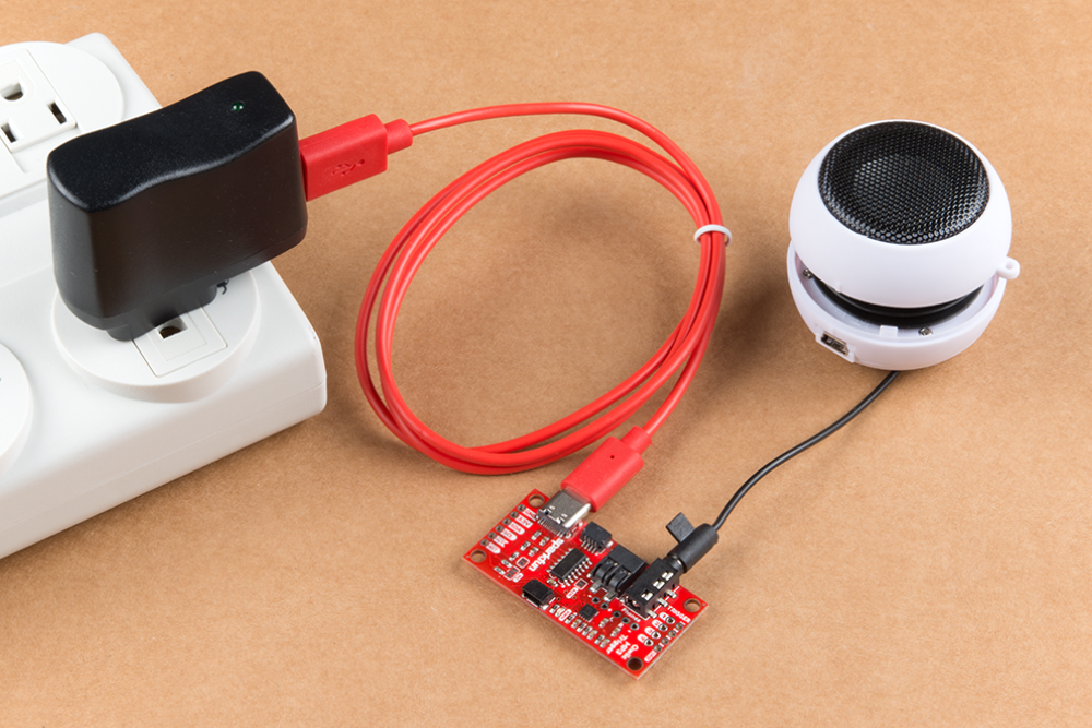
A standard 3.5mm audio jack is provided making it easy to play your tunes over headphones or amplified desktop speakers like our Hamburger Speaker or any other amplifier.
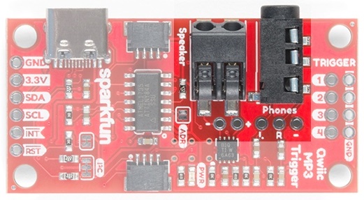
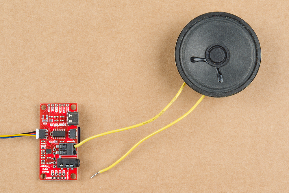
A poke-home connector labeled Speaker is also provided in parallel to the 3.5mm jack. This is a friction fit type connector; simply push stranded or solid core wire (22AWG or larger) into the hole and the connector will grip the wire.
To use an external speaker, solder two wires onto the speaker and insert the wires into the poke home connector.
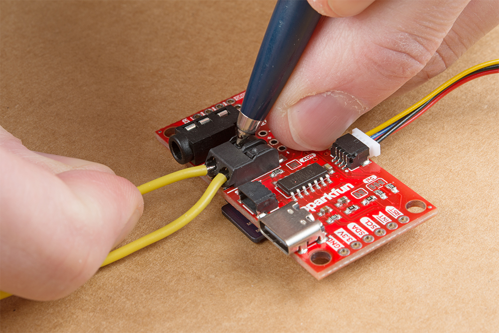
To remove, push down on the tab with a ballpoint pen and gently pull on the wire.
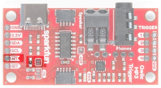
Jumpers
The Qwiic MP3 Trigger has three jumpers shown below:
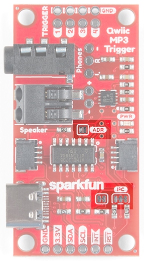
The default 7-bit I2C address of the Qwiic MP3 Trigger is 0x37. The ADR jumper is open be default and can be closed with solder to force the device’s I2C address to 0x36. This is handy if you need to have two Triggers on the same bus. If you need more than two devices on the bus, or if these addresses conflict with another I2C device the address can be changed in software. Please see the Command Set.
Cutting the I2C jumper will remove the 2.2k Ohm resistors from the I2C bus. If you have many devices on your I2C bus you may want to remove these jumpers. Not sure how to cut a jumper? Read here!
The INT jumper is located below the SparkFun logo and connects a 10K pull-up resistor to the INT pin. If you have multiple, open-drain, interrupt pins connected together you may want to remove this pull-up to better control the pull-up resistance.
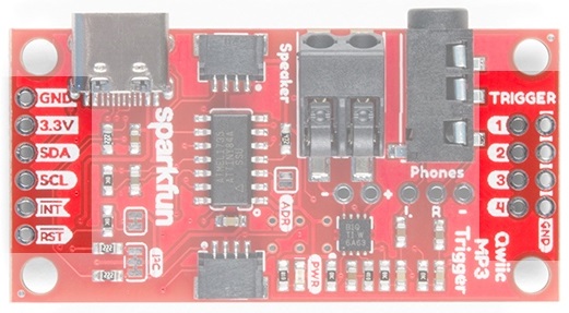
I/O Pins
There are several I/O pins broken out on the board, which are described in the table below.
| Pin Name | Type | Description |
|---|---|---|
| RST | Input | Active low. Pull this pin low to reset the ATtiny84A, effectively resetting the Qwiic MP3 Trigger. |
| INT | Output | Active low. Goes low when track is finished playing. Goes high again when CLEAR_INTERRUPTS command is issued. |
| SCL | Input | Serial clock line of I2C interface. Qwiic MP3 Trigger does implement clock stretching and will hold the clock line low if it is unable to receive additional I2C data. |
| SDA | Input/Output | Serial data line of I2C interface. |
| 3.3V | Power | Qwiic MP3 Trigger can be powered from 2.8V to 3.3V. Anything greater than 3.6V will damage the microSD card. |
| GND | Power | The ground pin. |
| Trigger 1-4 | Input | When a trigger pin is pulled to ground, the corresponding T00X.mp3 file is played. Pins can be combined to play T001 to T010. Pins are 5V tolerant. |
Triggers
There are four trigger pins at the top of the board. When pulled low these pins begin playing whatever file is named T001.mp3 to T010.mp3. For example, if you attach a momentary button to Pin 3 and GND, when you press that button the T003.mp3 file will immediately be played. This allows you to start playing sound effects with the touch of a button without any programming!
Single Trigger
For a basic triggered setup, load four files named T001.mp3, T002.mp3, T003.mp3, and T004.mp3 on the microSD card. Use a wire or button to connect a trigger pin to ground and the associated track will begin playing. Once you have the setup working, use any momentary button to allow a user to cause an MP3 to start playing.
Using Multiple Triggers
By pulling multiple pins down simultaneously the four triggers can play up to ten tracks: T001 to T010. When a trigger pin is detected the pin values are added together. For example, pulling pins 2 and 4 low at the same time will play track T006.mp3 as will pulling pins 1, 2, and 3 low at the same time.
- The trigger pins are constantly monitored and any change in pins will immediately cause the new track to begin playing.
- Indefinitely holding a pin low will cause the same track to play again. This allows for looping sound effects.
Interrupt Pin
The Qwiic MP3 Trigger has an INT pin which is configured as an open-drain pin with an on board 10K Ohm pull-up.
The INT pin will go low when a track has stopped playing. Once the CLEAR_INTERRUPTS 0x0D command has been received, the INT pin will become high-impedance and will return to a high level.
If you have multiple devices with bussed interrupt pins you may want to cut the INT jumper to remove the 10K pull-up resistor.
Qwiic MP3 Trigger Library
The SparkFun Qwiic MP3 Trigger Arduino library demonstrates how to control all the features of the Qwiic MP3 Trigger. We recommend downloading the SparkFun library through the Arduino library manager by searching 'SparkFun MP3 Trigger'. Alternatively you can grab the zip here from the GitHub repository:
Once you have the library installed checkout the various examples.
- Example1: Play the first MP3 track on the microSD card.
- Example2: Play the next track on the microSD card.
- Example3: Play a particular file. For example
mp3.playFile(3);will play F003.mp3. - Example4: Stop and pause tracks.
- Example5: Kitchen sink example showing setting of volume, equalizer, get song name, get song count, get firmware version, etc.
- Example6: Change the I2C address of the MP3 Trigger. Allows multiple Triggers to live on the same I2C bus.
- Example7: Shows how to start the library using a different Wire port (for example Wire1).
- Example8: Demonstrates how to check for the end-of-song interrupt and begin playing the song again.
Command Set
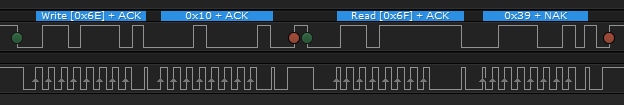
The SparkFun Qwiic MP3 Trigger library takes care of all these commands for you. However, if you want to implement your own interface, the following commands are available (see list below). The Qwiic MP3 Trigger uses standard I2C communication to receive commands and send responses. By default, the unshifted I2C address of the Qwiic MP3 Trigger is 0x37. The write byte is 0x6E and the read byte is 0x6F.
Here is an example I2C transaction showing how to set the volume level to 10:

Here is an example I2C transaction showing how to read the device ID (0x39):
The following commands are available:
- STOP
0x00- Stops any currently playing track - PLAY_TRACK
0x01 [TRACKNUMBER]- Play a given track number. For example 0x01 0x0A will play the 10th MP3 file in the root directory. - PLAY_FILENUMBER
0x02 [FILENUMBER]- Play a file # from the root directory. For example 0x02 0x03 will play F003.mp3. - PAUSE
0x03- Pause if playing, or starting playing if paused - PLAY_NEXT
0x04- Play the next file (next track) located in the root directory - PLAY_PREVIOUS
0x05- Play the previous file (previous track) located in the root directory - SET_EQ
0x06 [EQ_SETTING]- Set the equalization level to one of 6 settings: 0 = Normal, 1 = Pop, 2 = Rock, 3 = Jazz, 4 = Classical, 5 = Bass. Setting is stored to NVM and is loaded at each power-on. - SET_VOLUME
0x07 [VOLUME_LEVEL]- Set volume level to one of 32 settings: 0 = Off, 31 = Max volume. Setting is stored to NVM and is loaded at each power-on. - GET_SONG_COUNT
0x08- Returns one byte representing the number of MP3s found on the microSD card. 255 max. Note: Song count is established at power-on. After loading files on the SD card via USB be sure to power-cycle the board to update this value. - GET_SONG_NAME
0x09- Returns the first 8 characters of the file currently being played. Once the command is issued the MP3 Trigger must be given 50ms to acquire the song name before it can be queried with an I2C read. - GET_PLAY_STATUS
0x0A- Returns a byte indicating MP3 player status. 0 = OK, 1 = Fail, 2 = No such file, 5 = SD Error. - GET_CARD_STATUS
0x0B- Returns a byte indicating card status. 0 = OK, 5 = SD Error. Once the command is issued the MP3 Trigger must be given 50ms to acquire the card status before it can be queried with an I2C read. - GET_VERSION
0x0C- Returns two bytes indicating Major and Minor firmware version. - CLEAR_INTERRUPTS
0x0D- Clears the interrupt bit. - GET_VOLUME
0x0E- Returns byte that represents the volume level. - GET_EQ
0x0F- Returns byte that represents the EQ setting. - GET_ID
0x10- Returns 0x39. Useful for testing if a device at a given I2C address is indeed an MP3 Trigger. - SET_ADDRESS
0xC7 [NEW_ADDRESS]- Sets the I2C address of Qwiic MP3 Trigger. For example0x6E 0xC7 0x21will change the MP3 Trigger at I2C address 0x37 to address 0x21. In this example0x6Eis device address0x37with write bit set to 1. Valid addresses are 0x08 to 0x77 inclusive. Setting is stored to NVM and is loaded at each power-on.
Command Que
The ATtiny84A receives commands over I2C. It then records the I2C commands into a command que. The que is sent FIFO over serial to the WT2003S at 9600bps. The WT2003S then requires an undetermined amount of time to respond. This means that commands are not instantaneously executed by the Qwiic MP3 Trigger and some commands may require a certain amount of time to before the Qwiic MP3 Trigger has loaded a valid response.

For example, GET_SONG_NAME can be issued by the master microcontroller to the Qwiic MP3 Trigger. The QMP3 then transmits a serial command to the WT2003S. After a certain amount of time (unfortunately there are no max times defined by the WT2003S datasheet) the WT2003S will respond via serial. This can take 15 to 40ms. At that time, the song name will be loaded onto the Qwiic MP3 Trigger and can be read over I2C by the master microcontroller.
In order to avoid clock stretching by the Qwiic MP3 Trigger and tying up the I2C bus, the Qwiic MP3 Trigger will release the bus after every command is received. Therefore, it is up to the user to wait the minimum 50ms between the WRITE GET_SONG_NAME and the READ I2C commands.
Power Up Time
The MP3 decoder IC on the Qwiic MP3 Trigger is the WT2003S. It requires approximately 1500ms after power on to mount the SD card. Normally, the Qwiic MP3 Trigger is powered while the user writes and re-writes sketches so the user does not notice this boot time. The boot time only comes into effect when user initially powers their project. The main controller (such as an Uno) needs to wait up to 2 seconds before giving up communicating with the Qwiic MP3 Trigger. The SparkFun Qwiic MP3 Trigger library takes care of the 2 second wait but if you’re writing your own implementation then consider the following example code:
language:c
if (isConnected() == false)
{
    delay(2000); //Device may take up to 1500ms to mount the SD card

    //Try again
    if (isConnected() == false)
        return (false); //No device detected
}
return (true); //We're all setup!
Maximum Song Count
Up to 255 songs can be loaded onto Qwiic MP3 Trigger and triggered through the command interface.
Example 1: Play Track 1
The Qwiic MP3 Trigger can be used both as a standalone board or with the Qwiic connect system. In this case, we will be using the RedBoard Qwiic as the microcontroller in the Qwiic system.
For both options, make sure to load an MP3 file labeled T001.mp3 onto the MicroSD card.
T002.mp3 to associate it with Trigger Pin 2.
Standalone: Using Trigger 1
By default the firmware installed on the ATtiny84 allows you to play tracks using the triggers. For more details, see the Triggers section of the Hardware Overview. Simply plug in the SD card, power the Qwiic MP3 Trigger, and short the Trigger Pin 1 to GND. Everytime you short both pins, T001.mp3 will play.
Arduino Library: Using RedBoard Qwiic
Plug in the SD card into the MP3 Trigger. Then, connect the Qwiic MP3 Trigger to the RedBoard Qwiic using a Qwiic cable.
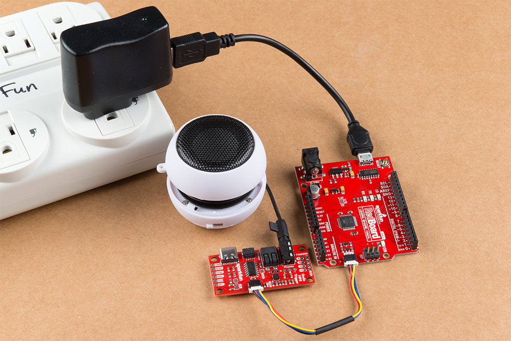
Upload Example1-PlaySong.ino using the Arduino IDE to the RedBoard Qwiic. Once uploaded, the RedBoard will check for the Qwiic MP3 Trigger, set the volume to 10 and then play T001.mp3. Pressing the RESET button on the RedBoard will run the sketch again.
Resources and Going Further
Have fun with your new tunes maker!
For more on the Qwiic MP3 Trigger, check out the links below:
- Schematic (PDF)
- Eagle Files (ZIP)
- WT2003S Datasheet (PDF)
- Qwiic Landing Page
- SparkFun Qwiic MP3 Trigger Arduino Library
- Example Sketches (ZIP)
- Qwiic MP3 Trigger Repo
- SFE Product Showcase
Need some inspiration? Check out some of these related tutorials:
MP3 Player Shield Music Box
Sound Page Guide
Photon Battery Shield Hookup Guide
Check out these other Qwiic tutorials:
Qwiic 12-Bit ADC Hookup Guide
Garmin LIDAR-Lite v4 (Qwiic) Hookup Guide
Getting Started with the Autonomous Kit for the Sphero RVR
Qwiic Carrier Board Hookup Guide
Or check out these blog posts: