Qwiic Digital Indoor Thermometer
 bboyho
Hardware Hookup
The Qwiic ecosystem has made it easier and faster to prototype. You simply connect a Qwiic device to an Arduino using a Qwiic cable. We can add additional Qwiic devices to the I2C bus with ease. The original tutorials use a RedBoard Qwiic with an ATmega328P to connect to each device. In this project tutorial, we'll use the Qwiic Micro with SAMD21 to make it as small as possible.
We will use the Qwiic TMP117 to measure the ambient room temperature. However, if you do not require such precision, you can also use the Qwiic TMP102. We will use the Qwiic micro OLED to display the temperature.
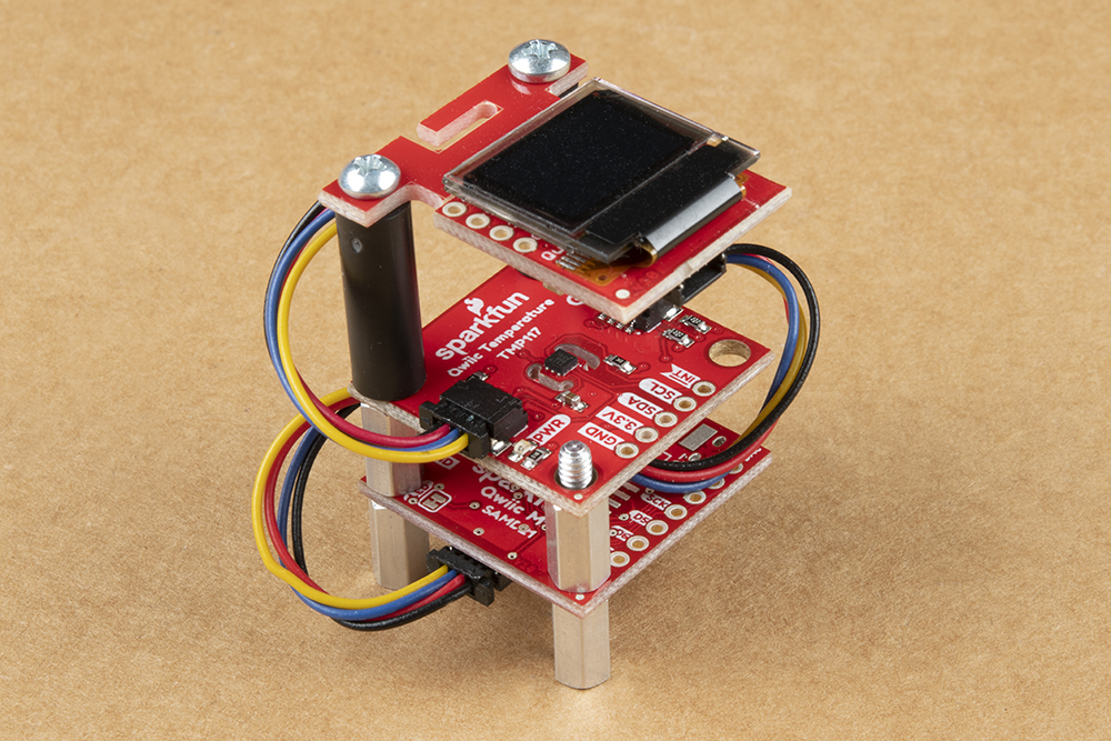
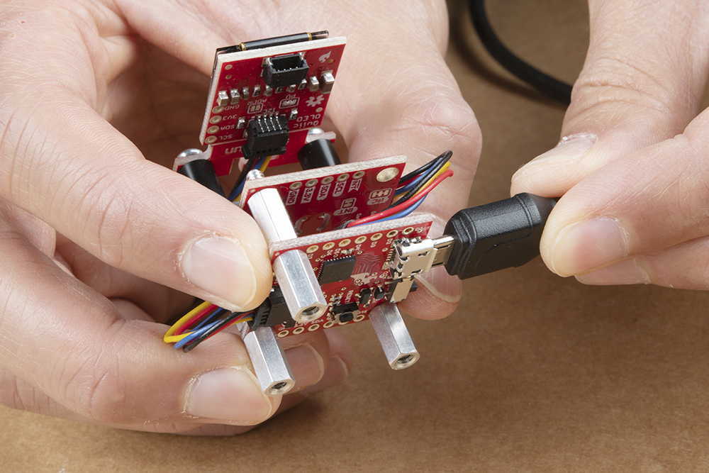
Once the boards are daisy chained, there is an option to mount the boards using the mounting holes located on the standard 1.0"x1.0" sized Qwiic boards. We'll be stacking the Qwiic boards on top of each other using standoffs and any available mounting holes with the Qwiic micro OLED on top, Qwiic TMP117 in the middle, and the Qwiic micro on the bottom. Note that the top of the Qwiic Micro in this tutorial will face away from the other boards so that we can easily access the reset button. However, you can face it however you would like based on your personal preference. When you are ready, connect the USB cable to Qwiic Micro. We will use this to power and program the board.