Qwiic 12-Bit ADC Hookup Guide
 QCPete, santaimpersonator
Arduino Examples
Example 1: Read Basic
The code for Example1_ReadBasic.ino connects to the Qwiic 12-bit ADC and prints out the value of channel A3 over the Serial Monitor at BAUD 9600. Below is a sample readout from the Serial Monitor rotating the onboard trimpot from MIN (all the way CCW) to MAX (all the way CW), and then back to MIN again. Notice how it "maxes out" at 2047, this is because the trimpot is inputing voltages from 0 to 3.3V. And with the default gain of 2 the input range of the ADC is only up to 2.048V.

Example 2: Change Gain
The code for Example2_ChangeGain.ino operates exactly like the Example1_ReadBasic.ino, except the gain is set to 1. This means that it can now accept voltages from 0 to 4.096V with a resolution of 2mV. Below is a sample readout. Notice how when rotating the trimpot (0-3.3V), I can only get the reading up to 1651. This is because we are not reaching the top of the ADC's range (at this gain of 1).
Example 3: Address
The code for Example3_Address.ino connects to your Qwiic ADC on a specific address. You must modify the address jumper located on the bottom side of the board. Cut the trace connecting the default jumper, and then close the jumper that is labeled with the desired address. Example3_Address.ino works the same as Example1_ReadBasic.ino, however it passes an address argument to the .begin() function like so: adcSensor.begin(0x49);

Example 4: Differential
The forth example, Example4_Differential.ino, shows how to read the ADC in differential mode using channels A0 and A1. For this example, I am using two trimpots (tied to GND and 3.3V) to supply voltage sources to A0 and A1. I have the A0 trimpot set to 2.5V, and it will stay there as a reference. In the readout below, I am rotating the A1 trimpot from 0V all the way up to 3.3V. You can see that I actually start at a negative value, because my rotating trimpot is actually sitting at 0V (or negative 2.5 Volts in relation to the other input).

Example 5: Alert
The code for Example5_Alert.ino sets up a single ended comparator in the ADS1015 chip. It is watching A3, and it if it sees a value about the threshold of 1000 (about 3V), it will drop the ALERT pin. The serial monitor below shows state of the alert pin (as read from D2) and the value from the ADC. This shows that when you cross 1000, then the alert pin changes accordingly.

Example 6: Display MilliVolts
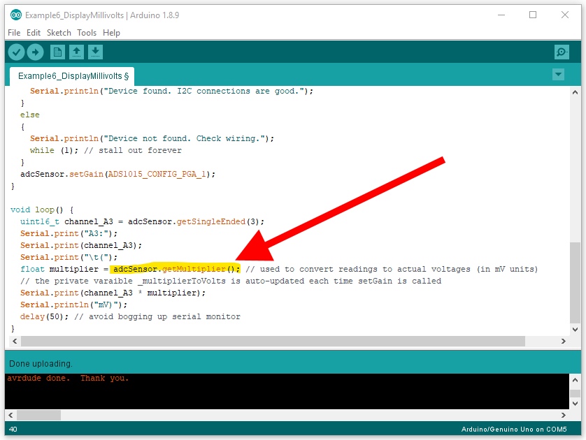
The last example, Example6_DisplayMillivolts.ino, will work much like Example1_ReadBasic.ino, however it also will print out the reading in millivolts. To convert from the raw reading values from the ADC, you must use a multiplier to get to millivolts. This changes depending on what gain setting you are using. For ease of use, we have included a function in the library that looks at your current gain settings, and then returns the correct multiplier you need. It is named .getMultiplier().
In the following serial monitor readout, you can see me turning the on-board trimpot on A3 (from 0V up to 3.3V) as it prints out both the return values and millivolts.