QRD1114 Optical Detector Hookup Guide
 jimblom
 Introduction
The QRD1114 is a half-LED, half-phototransistor, all infrared reflective optical detector. It can be used to sense objects in close proximity or even detect the difference between black and white surfaces. Photodetectors like these are critical components for projects ranging from line-following robots to close-proximity detection in smartphones.
The QRD1114 is easy to hook up: All you need is a current-limiting resistor for the IR LED and a pull-up resistor on the phototransistor's collector pin. The component can be used to produce an analog signal -- read by a microcontroller's analog-to-digital converter pin -- proportional to a nearby object's proximity.
Suggested Materials
This tutorial serves as a quick primer on reflective photodetector's and demonstrates how to hook them up and use them. Beyond the sensor itself, the following materials are recommended:
Arduino Uno -- We'll be using the Arduino's analog-to-digital converter to read in the analog output voltage of the photodetector. Any Arduino-compatible development platform -- be it a RedBoard, Pro or Pro Mini -- can substitute.
Resistor Kit -- The LED portion of the photodetector requires a current-limiting resistor -- somewhere in the range of 330Ω. On the other half of the sensor we'll need a 10kΩ pull-up resistor to take advantage of the phototransistor's light-dependent current throughput. This resistor kit is handy for some trial-and-error testing to hone in on the most sensitive circuit possible.
Breadboard and Jumper Wires -- The photodetector's legs can be bent and shaped to fit a standard 0.1"-spaced breadboard. We'll then use the jumper wires to connect from breadboard to Arduino.


Suggested Reading
Reflective photodetector's are a great entry-level component for beginners, but there are still a few basic electronics concepts you should be familiar with. If any of these tutorial titles sound foreign to you, consider skimming through that content first.
Light
Analog to Digital Conversion
Light-Emitting Diodes (LEDs)
Transistors
QRD1114 Overview
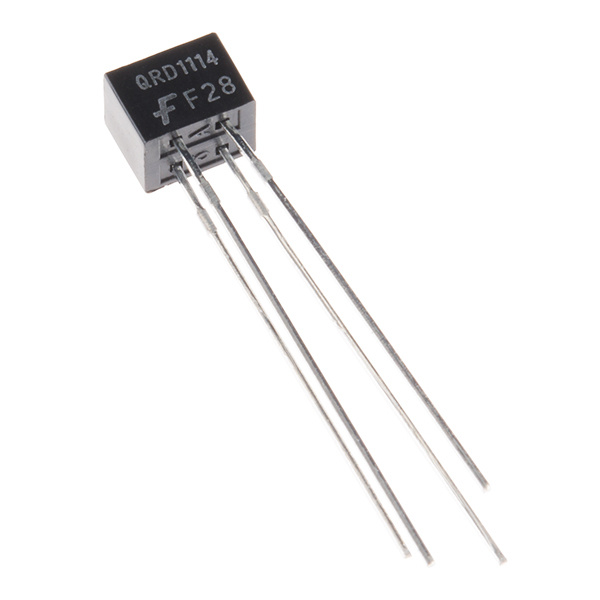
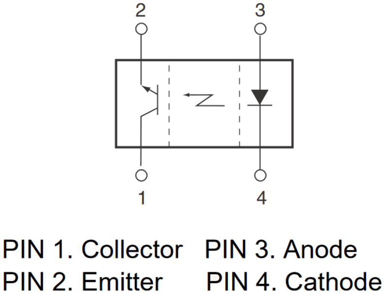
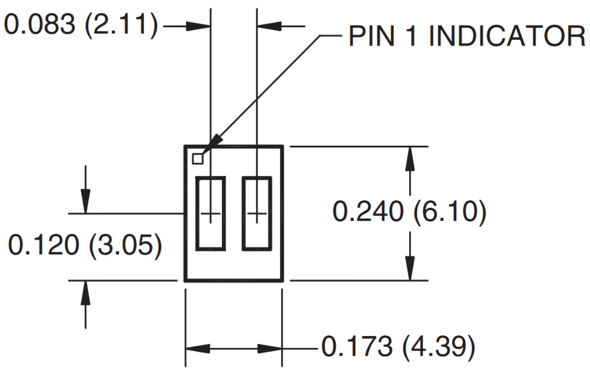
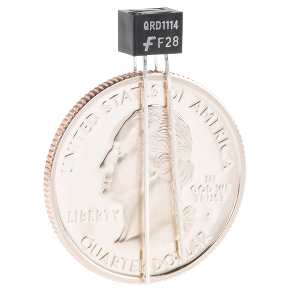
The QRD1114 is a 4-pin device. Two legs break out the infrared LED, and the other two legs break out the collector and emitter pins of the phototransistor (the "base" of the phototransistor is controlled by the IR light returned). The image below, from the datasheet, shows which pin is which.
Pin 1, the collector of the transistor, can be found by locating the dot on the top of the component. You should also be able to see two noticeably different-colored rectangles -- one black and one clear. The black rectangle is the phototransistor (the black part is actually a filter cover), and the clear half is the LED.
Looking from the top down, the pins increment in counter-clockwise order. Pin 2 -- the transistor's emitter -- is adjacent to pin 1 along the long side of the body. Pin 3, the LED anode is across the short side of the photodetector from pin 2. And the cathode pin 4 is next to pin 3 and across the body from pin 1.
The length of the legs can also help determine which pin is which. Pins 1 and 3 are longer than the other pins; (probably) not coincidentally, these are the "positive" pins of their respective components (collector and anode).
Sensor Characteristics
The QRD1114's infrared LED is just like any other LED you may have used in the past. The forward voltage is typically between 1.2V and 1.7V, which means you'll need at least that much potential on your supply to power the LED. 3.3V or 5V supplies can work just fine, as long as you have a current-limiting resistor.
The LED's maximum forward current is 50mA; more than that has a chance of permanently damaging the part. It's best to aim at delivering around 20mA to the diode.
One of the most interesting graphs in the QRD1114 datasheet is this distance versus transistor collector current curve:
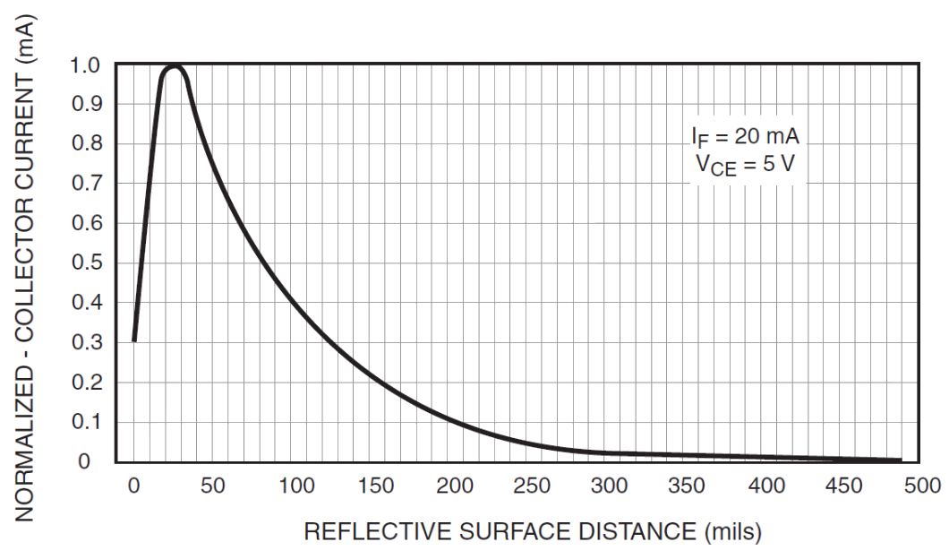
The graph above makes assumptions (LED intensity, power to the across the transistor, reflecting material), but it's still a good gauge for estimating a distance based on the output signal. It at least demonstrates a few things about the sensor:
- The output tops out at about 30 mils (0.03", 0.76mm).
- From the peak, it slopes down exponentially.
- At about 125 mil (0.125", 3.18mm), the output signal is already 30% of the peak.
- At about 300 mil (0.3", 7.62mm), changes in the signal become nearly indistinguishable.
- If an object gets too close to the sensor, it will enter a dead zone. Anything closer than about 30 mils (0.03", 0.76mm) is difficult for the detector to see.
TLDR: these sensor's don't have a very large range. They're designed for close proximity sensing. They can reliably detect distances ranging from 0.03 to about 0.4 inches (0.75-10.15mm).
Example Circuit
Incorporating a 330Ω current-limiting resistor and a 10kΩ pull-up resistor, here's an example circuit connecting the QRD1114 to an Arduino:
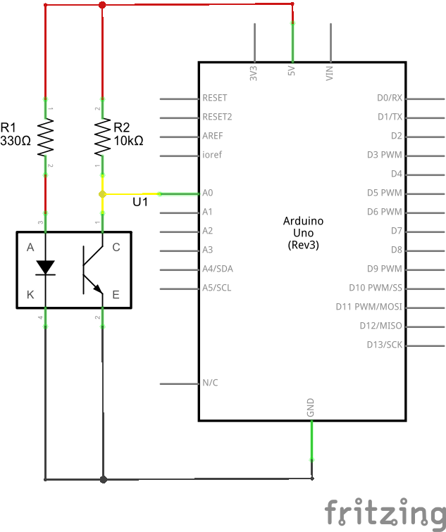
The LED is supplied by 5V with a 330Ω current-limiting resistor. The value of this resistor can be decreased to around 175Ω to increase the LED current closer to 20mA.
The transistor's emitter is grounded, and the collector is connected to the Arduino's A0 pin. The 10kΩ pull-up resistor helps turn the transistor's light-variable current into a light-variable voltage.
Here is an example breadboard wiring diagram for the circuit:
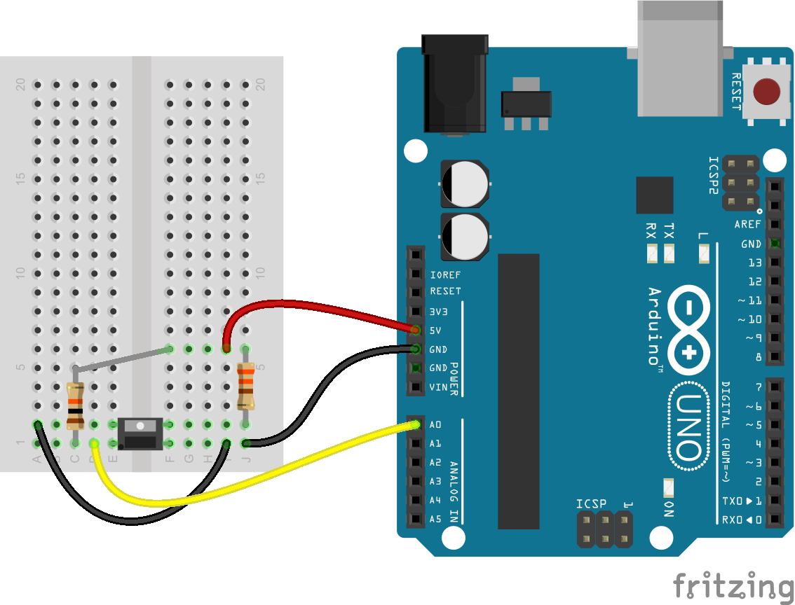
There are many ways to assemble this circuit on a breadboard. The example above straddles both the LED and phototransistor across the breadboard's median.
Example Code
Here is a simple Arduino example based on the circuit above. Copy and paste this into your Arduino IDE, then upload!
Note: This example assumes you are using the latest version of the Arduino IDE on your desktop. If this is your first time using Arduino, please review our tutorial on installing the Arduino IDE.
If you have not previously installed an Arduino library, please check out our installation guide.language:c
/******************************************************************************
QRD1114_Proximity_Example.ino
Example sketch for SparkFun's QRD1114 Reflectance Proximity Sensor
(https://www.sparkfun.com/products/246)
Jim Lindblom @ SparkFun Electronics
May 2, 2016
Connect a QRD1114, 330 resistor and 10k resistor as follows:
QRD1114 Pin ---- Arduino ---- Resistors
1 A0 10k Pull-up to 5V
2 GND
3 330 Resistor to 5V
4 GND
As an object comes closer to the QRD1114, the voltage on A0 should go down.
Development environment specifics:
Arduino 1.6.7
******************************************************************************/
const int QRD1114_PIN = A0; // Sensor output voltage
void setup()
{
Serial.begin(9600);
pinMode(QRD1114_PIN, INPUT);
}
void loop()
{
// Read in the ADC and convert it to a voltage:
int proximityADC = analogRead(QRD1114_PIN);
float proximityV = (float)proximityADC * 5.0 / 1023.0;
Serial.println(proximityV);
delay(100);
}
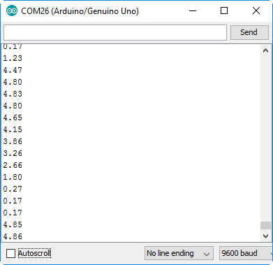
After uploading, open your serial monitor, and set the baud rate to 9600 bps.
While you monitor the voltage outputs in the serial monitor, move your hand towards the sensor's head. You should see the voltage dip from ~4.8V to less than 0.2V. Keep moving in and out to get a feel for the sensor's viewing distance.
After testing it out with your finger, try testing other objects. In addition to distance, the output voltage also depends on the object's color and reflectance. As an example, here's a very unscientific comparison we did between black and white sheets of paper:
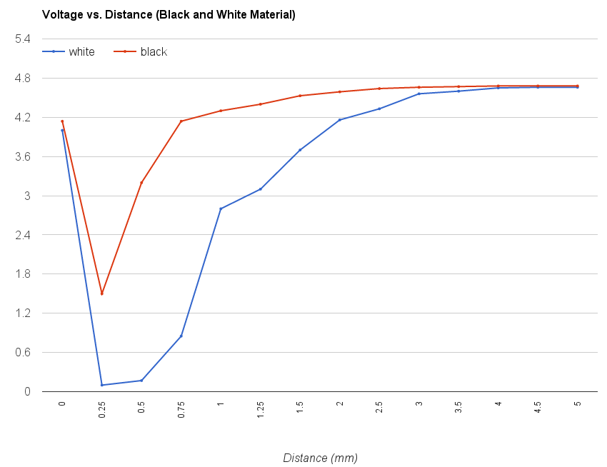
The sensor is much more sensitive to the white paper than the black. The black surface absorbs more light from the LED, meaning less is reflected back to the phototransistor. Try doing some science of your own to test out your sensor's behavior!
Resources and Going Further
For more information on the QRD1114, be sure to check out the datasheet.
Now that you've got your Arduino sensing proximity, and even color, what project are you going to create? Need some inspiration? Check out some of these related tutorials: