Proto Pedal Chassis Hookup Guide
 Byron J.,
  MTaylor
Laying Out The Holes
Before drilling, we need to figure out where to locate the holes.
This is an exercise in three-dimensional thinking. We need to account for the location of the controls on the panel, as well as the clearance above and below. Above the surface of the pedal, you'll probably want to leave some room around the controls, so you can grab them. Inside the chassis, you need to consider where the internal portion of the control will be located, especially in relation to the taller components on the PCB.
Rough Layout
In this example, we wanted to put five potentiometers on the chassis. We simply moved the knobs around on top of the chassis until we reached a reasonable arrangement. Notice that we're leaving clearance for the TRS jacks.
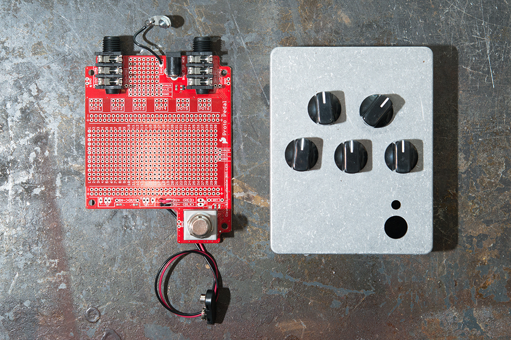
We had the circuit board nearby to use as a reference, to help see where internal objects are are located. We also had the assembled stack of Teensy 3.2 and Audio Adapter nearby, which we test fit several times as we worked. This allowed us to recognize that the stack doesn't stand much above the board, leaving vertical space to place a pot over it.
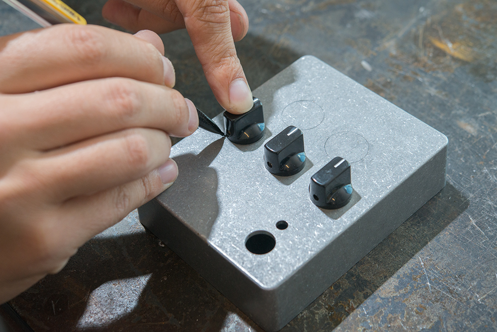
With the knobs in rough proximity of their ultimate destinations, we traced them in pencil, making circles on the box.
More Precise Layout
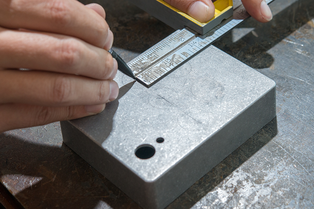
With the knobs removed, we measured the location of their centers from the top edge of the box. We averaged the measurements, so the holes would be in reasonable alignment.
Here we've marking a line 2 1/2 inches from the top edge, using a combination square to insure a consistent distance. If you don't have a square, you can carefully measure two points and draw a line between them.
The top row is an inch closer to the edge, at 1 1/2 inches.
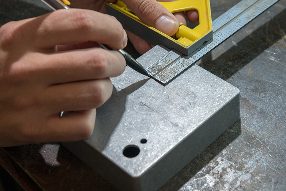
With the lines for the rows drawn, we'll move on to the horizontal position of each pot within the rows.
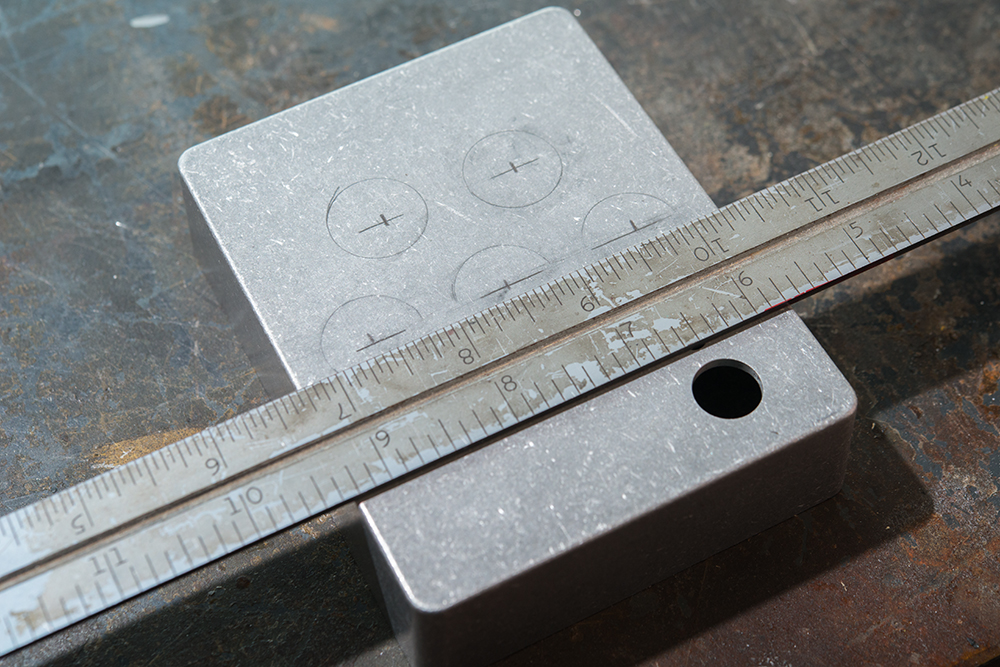
We decided to center these knobs, so we set the ruler on the box such that the edges aligned the same number of subdivisions past the last whole inch, or a little more than 1/4 inch, at 9 1/4 and 5 3/4. Now, the 8 1/2 inch mark is centered horizontally and we can count subdivisions out from there to make sure the holes are equally spaced.
The top row holes were marked 1/2 way between the marks in the bottom row, resulting in a regular "M" shape.
Notice that the rough knob outlines are no longer accurate to the center marks. The outlines were just eye-balled on for aesthetics, while the measured marks insure accuracy.
Punching
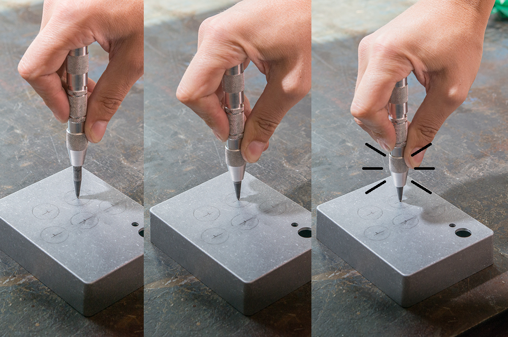
Punch the center of each hole. This will help guide the drill bit.
If you've never seen a spring loaded center punch before, they're really cool. Just press down until the internal spring is sprung, and it leaves a mark behind. You can get these at most hardware stores.
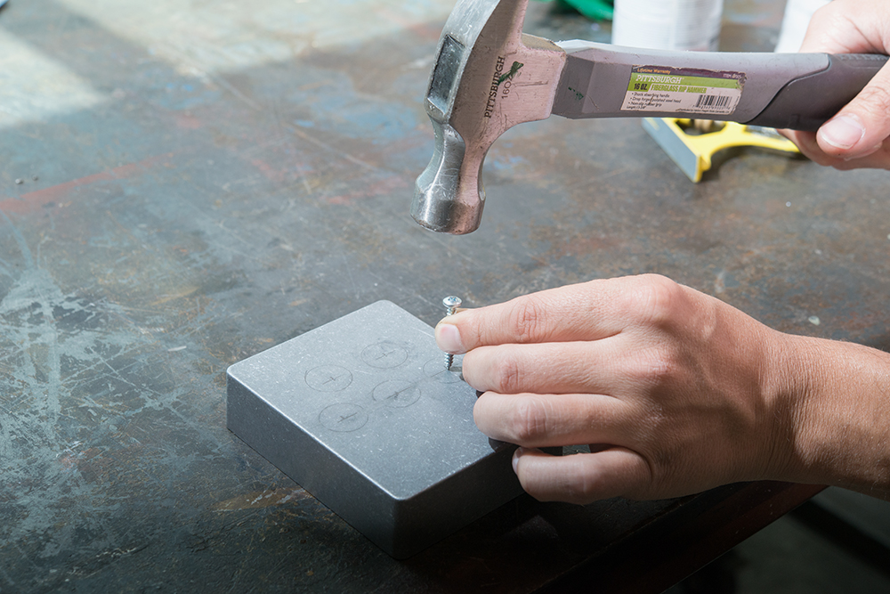
Or if you don't have a center punch, use a large screw and a hammer. Big pan heads work well, but wood deck screws or drywall screws are too pointy.
Now let's get to the real action!