Proto Pedal Chassis Hookup Guide
 Byron J.,
  MTaylor
Extra holes for the Teensy
For the Teensy based digital pedal, we're going to add a couple extra holes. The first is one on the side of the chassis for the USB connector, plus a second smaller hole in the top of the pdeal, so we can reach the manual-load button.
As with our initial layout, we're going to do it empirically, using the final parts to gauge where the holes need to be. We started with the USB port, measuring on the left side of the enclosure.
Programming Port
First, choose the location of the programming hole based on where you want the Teensy to be in the pedal. Use the circuit board as a guide, aligning the 1/4 inch jack shoulders to the inside plane.
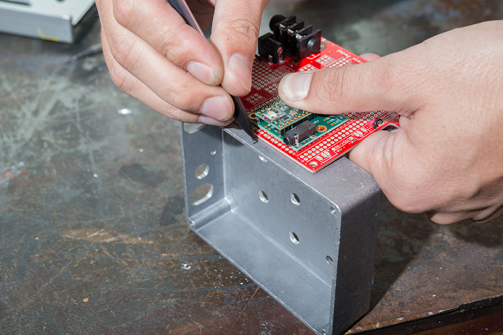
Approximate the height of the hole by holding the circuit board where it will sit when assembled, and cross the previous mark.
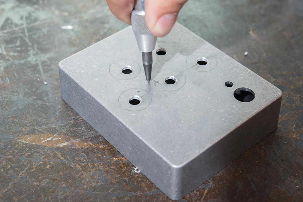
Then, punch a center point, and move on to drilling.
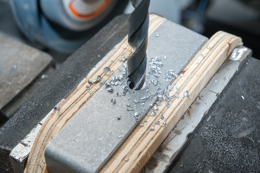
We going all the way up to our largest drill, to accommodate the USB plug molding, making 4 drills overall. This time, were using a vice to hold the workpiece, again using blocks of wood to protect it.
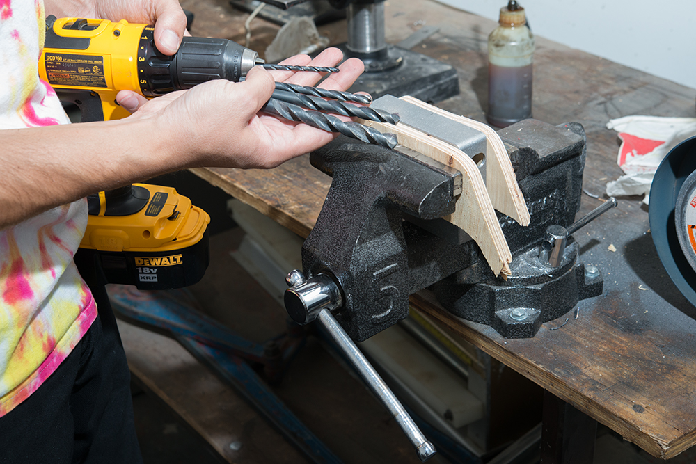
As before, we're working progressively up to the larger drills.
Since this hole is larger, there will be two intermediate drills.
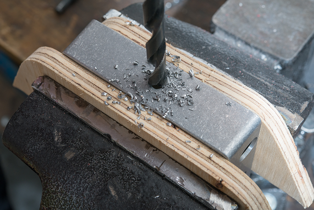
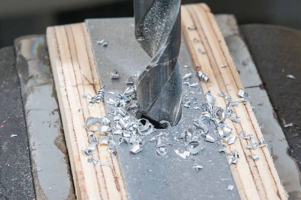
Watch the quality of the waste material. It's a good sign that speeds and pressures are correct when the waste forms into curls rather than little chips. Also, it can be seen here that the overlap is quite small for this large bit. Otherwise, the bit would have a great tendency to catch when getting close to being through.
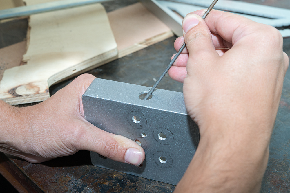
Once the drilling is complete, we want to chamfer the edges of the hole. The chamfer is more important for this hole, because the sharp edge won't be covered with a control. This time, the hole is as large as the bit were were chamfering with before, so we have to do it manually, with a file.
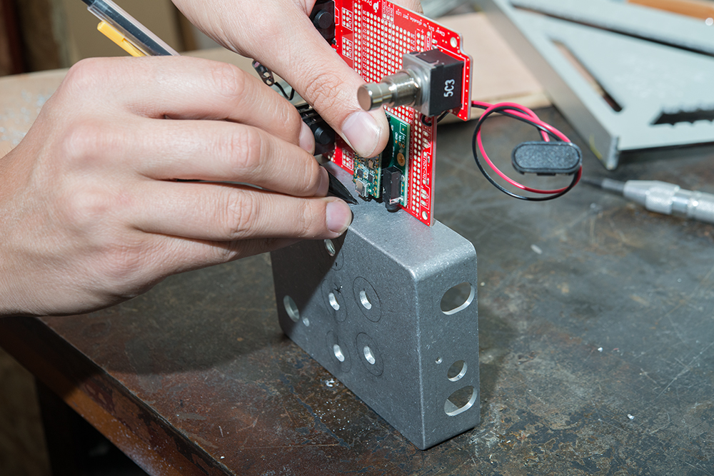
Reset Switch
We used a similar triangulation process for the hole for the button. Here, there's a mark where it should be, but that is underneath a knob. The hole was moved outside of the knob outlines, and will have to be used at a slight angle.
Since this hole is smaller, we didn't need to step through as many drills.