Contributors:
 jimblom
 Board Overview
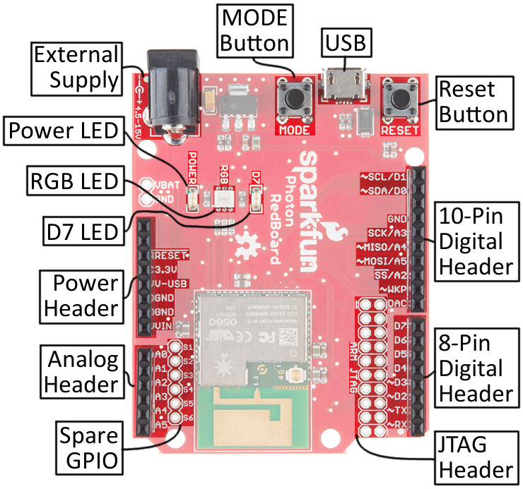
The Photon RedBoard is a mash-up of the Particle Photon and the SparkFun RedBoard. There are features from each of those boards in the layout:
For a quick summary of the board's components:
- External Supply: A barrel jack power supply can be used to power the Photon with a voltage between 4.5-15V.
- LEDs
- Power: A red LED indicates that the board is receiving power.
- RGB: This LED displays the state of the Photon RedBoard's P1 module -- whether it's connected, connecting, or in DFU mode.
- D7: This LED is attached to the Photon's D7 pin. It's a handy debugging tool.
- Headers
- Power: The power header delivers GND, 3.3V, USB voltage (~4.8V), and the external supply voltage (VIN).
- Analog: Six of the Photon's analog-to-digital (ADC) pins are broken out here.
- 8-pin Digital: The Photon's hardware UART (RX & TX) and digital pins D2-D7.
- 10-pin Digital: A mish-mash of unique pins -- like the digital-to-analog output (DAC) -- plus SPI and I2C interfaces.
- Spare: Bonus GPIO! These "spare" pins aren't enabled in the Particle firmware yet, but it's coming.
- Buttons
- Reset: The reset button can be used to re-start the Photon module.
- Mode: To switch between running, safe, listening, and DFU modes.
- USB Connector: USB can be used to power the Photon RedBoard, but it can also be used as a serial data interface.
- JTAG Header: The 20-pin JTAG header matches the pinout for an ST-Link/v2 JTAG in-circuit debugger/programmer.
Photon I/O Pins
The Photon pinout doesn't exactly match an Arduino -- there just aren't enough pins. But the pins that are broken out have all sorts of extra functionality. Here's a summary of each of the pins and their capabilities:
| Pin Label |
Name(s) – Function(s)
(Alternate names bolded) |
Analog Output (PWM)? |
5V Tolerant Digital Input? |
| A0 |
|
|
✔ |
| A1 |
|
|
✔ |
| A2 |
|
|
✔ |
| A3 |
|
|
| A4 |
|
✔ |
✔ |
| A5 |
|
✔ |
✔ |
|
| RX |
|
✔ |
✔ |
| TX |
|
✔ |
✔ |
| D2 |
| MOSI (SPI3) |
CAN RX |
I2S SD |
|
✔ |
✔ |
| D3 |
|
✔ |
✔ |
| D4 |
| SCK (SPI3) |
I2S SCK |
JTAG TDO |
|
|
✔ |
| D5 |
| SS (SPI3) |
I2S WS |
JTAG TDI |
|
|
✔ |
| D6 |
|
|
✔ |
| D7 |
|
|
✔ |
|
| DAC |
|
|
|
| WKP |
|
✔ |
✔ |
| SS/A2 |
|
|
✔ |
| MOSI/A5 |
|
✔ |
✔ |
| MISO/A4 |
|
✔ |
✔ |
| SCK/A3 |
|
|
|
|
| SDA/D0 |
|
✔ |
✔ |
| SCL/D1 |
|
✔ |
✔ |
|
| Analog In |
SPI1 |
SPI3 |
DAC |
I2C |
CAN |
JTAG |
I2S |
|
Differences Between Photon RedBoard and Arduino Pinout
The Photon RedBoard maps most digital, analog, and serial interfaces to its Arduino equal, but there are a few significant differences.
There are no explicitly digital Photon pins beyond D7, so you won't find D8, D9, D10, D11, D12, or D13. The Photon RedBoard breaks out DAC, WKP, SS/A2, MOSI/A5, MISO/A4, and SCK/A3 in their place.
Double vision: A2, A3, A4, and A5 are broken out twice on the Photon RedBoard! They can be found, obviously, on the analog input header. But those pins also serve as the Photon's hardware SPI port, so they're also broken out on the 10-pin digital header (and labeled with their SPI purpose). More on that in the
Arduino Shield (In)Compatibility section.
The hardware UART pins -- labeled RX and TX -- are broken out where you would expect to see D0 and D1. These pins can be used with the Photon's Serial1 class, or as digital inputs or outputs. For example...
language:c
pinMode(RX, OUTPUT); // Set RX pin as a digital output
digitalWrite(RX, HIGH); // Write RX pin HIGH
...will set the RX pin high.
The DAC and WKP pins serve as the Photon's main digital-to-analog output and wake-from-sleep input, respectively. But they can also be used as analog inputs or digital inputs/outputs. To use the DAC pin as a analog or digital I/O, reference it as A6; the WKP pin can be referenced using A7.
| Pin Label |
Alternate Analog Pin |
| WKP |
A6 |
| DAC |
A7 |
The I2C pins at the top of the 10-pin header -- SDA/D0 and SCL/D1 -- are where you'd expect to see them on any Arduino board (unless it's a really old Arduino). These pins can also be digitally referenced with D0 and D1 -- don't confuse them with the RX and TX pins, though!
Also note that there is no AREF pin on the Photon RedBoard -- that pin is left as not-connected (and not labeled).
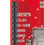
Power Supply Header
The 8-pin power header breaks out three possible voltage supplies, plus ground and RESET -- the Photon's active-low reset signal.
Here's a quick reference for the three voltage supplies on the header:
| Pin Label | Nominal Voltage | Voltage source | Current Output Limit |
|---|
| 3.3V | 3.3V | 3.3V regulator output | 800mA |
|---|
| V-USB | 4.8V (5V minus a diode drop) | USB | 500mA (fused) |
|---|
| VIN | 4.5-15V | Barrel Jack | Depends on external supply |
|---|
3.3V! The Photon operates at 3.3V -- it is not capable of running at 5V! Most digital pins are 5V tolerant, when configured as inputs, but the analog pins are not!
RGB LED
The RGB LED on the Photon RedBoard identifies the connectivity status -- or other state information -- of the P1 module. The color-to-mode mapping of the Photon RedBoard is described in detail in Particle's Device Mode documentation. As a quick summary:
| LED Color | LED activity | Device Mode |
|---|
| Cyan | ● | Breathing | Connected to WiFi and Particle Cloud |
| Cyan | ● | Blinking | Connected to WiFi, Connecting to Particle Cloud |
| Green | ● | Blinking | Connecting to WiFi |
| Blue | ● | Blinking | Listening mode (waiting for WiFi info) |
| Pink | ● | Blinking | Receiving new application over-the-air |
| Pink | ● | Breathing | Connected in safe mode |
| White | ● | Breathing | Application running, WiFi off |
| Orange-Yellow | ● | Blinking | DFU mode |
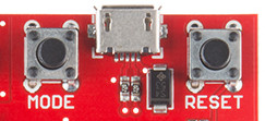
MODE and RESET Buttons
The RESET button -- as with RESET buttons you may already be familiar with -- can be used to restart the Photon RedBoard's application. After pressing and releasing the button, the Photon will begin to boot up from scratch, which means it'll have to re-connect to WiFi.
The MODE button can be used to place the Photon in any number of diagnostic modes, described in the Photon device mode documentation. It can be used to boot into safe mode (connected to WiFi/Cloud, but no application running), DFU mode, or to factory reset the device.
To place the Photon in any of those modes, begin by holding both RESET and MODE down. Then release RESET, while still holding MODE. Release the MODE button to leave the Photon RedBoard in the desired state.
The MODE button can also be used to place the Photon in listening mode (to re-configure WiFi, check the firmware version, or module identity), while an application is running. To accomplish that, hold the MODE button down for about 4-5 seconds, until the RGB LED begins blinking blue.
Spare I/O Pins
Compared to the Photon's P0 module, the P1 on the Photon RedBoard delivers six extra GPIO pins. These are labeled as "spare" GPIO, and broken out near the analog header. "S1" corresponds to "SPARE1", "S2" is "SPARE2", and so on.
This header is not equipped with a connector -- soldering to the pins is left to the user.
At this time the spare GPIO are not implemented in Photon firmware, but they should be usable in future releases.