Photon RedBoard Hookup Guide
 jimblom
Arduino Shield (In)Compatibility
One of the Photon RedBoard's most unique feature's is its familiar Arduino-shaped form-factor, which makes it -- at least mechanically -- compatible with most Arduino shields. Unfortunately, there's a big difference between mechanically compatible and electrically.
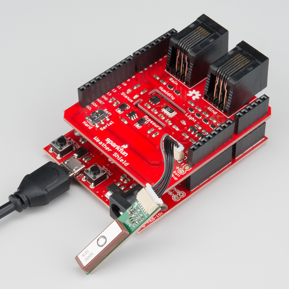
Some Arduino shields will work with the Photon RedBoard, but many others will not. Here's what to watch out for when you consider loading the RedBoard with a shield:
3.3V Logic
The most important distinction between an Arduino Uno and the Photon RedBoard is the operating voltage. The Photon RedBoard's P1 module operates at 3.3V. That means the I/O pins will also operate between 0-3.3V. If a pin is configured for digital output, it will produce 3.3V for a logic HIGH and 0V for a logic LOW.
The power header does supply all of the voltage's you'd expect. The V-USB pin should supply about 5V (it'll be closer to 4.8V). VIN will either supply about 4.5V when powered by USB, or -- if a barrel jack supply is connected -- the direct voltage supplied from the external jack.
D8-D13 and Duplicated A2-A5
A second key difference between an Arduino Uno and the Photon RedBoard is the RedBoard's lack of explicit GPIO from D8-D13. Where you'd usually expect to see those labels, you'll instead find a combination of unique GPIO and duplicated analog pins -- providing a hardware SPI port.
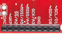
Also note that, instead of D8 and D9, the DAC and WKP pins are broken out. While they have unique functions themselves, these pins can be used as digital inputs or outputs, or even analog inputs! You'll just need to remember to invoke them by their equivalent analog pin names: A6 (DAC) and A7 (WKP).
Mismatched Analog Output Pins
In total, the Photon RedBoard offers more analog (PWM) outputs than an Arduino Uno, but those analog outputs aren't all in the same spot. The table below provides a quick reference to matched, unmatched, and extra PWM:
| Arduino PWM Pins | Photon RedBoard PWM Pins | |
|---|---|---|
| – | RX (D0 position) | |
| – | TX (D1 position) | |
| – | D2 | |
| D3 | D3 | |
| D5 | – | |
| D6 | – | |
| D9 | WKP (D9 position) | |
| D10 | – | |
| D11 | MOSI/A5 (D11 position) | |
| – | MISO/A4 (D12 position) | |
| – | SDA/D0 (SDA position) | |
| – | SCL/D1 (SCL position) | |
| Photon Only | Arduino Only | PWM Match |
Pins 5, 6, and 10 -- usually equipped with PWM on an Arduino -- can not be used for analogWrite()'ing. But there are a number of bonus PWM pins, in the D0, D1, D2, D12, SDA, and SCL positions!
D0, D1, RX, and TX
Most of the digital pins from 0 to 7 are right where you'd expect them -- all of them except D0 and D1. In place of D0 and D1 are the Photon's hardware UART pins: RX and TX.
In code, these serial pins can be controlled with the Serial1 object (don't forget the '1' -- Serial without the '1' is the USB port serial).
The RX and TX pins can also be used as digital inputs or outputs. Simply use their labeled names to control or read their state. For example:
language:c
pinMode(RX, OUTPUT); // Set RX as an output
digitalWrite(RX, HIGH); // Write RX high
pinMode(TX, INPUT); // Set TX as an input
int txState = digitalRead(TX); // Read TX's logic level
Serial.print("TX's status is: " + String(txState)); // Print TX's logic level over USB
D0 and D1 do still exist in Photon RedBoard world! They're the alternative names for the I2C pins, at the top of the 10-pin digital header. The can be controlled using either D0 and D1 or SDA and SCL.
I2C Pins -- Not on A4/A5
If you're a veteran Arduino developer, you may remember a time -- before the Arduino Leonardo -- when there weren't explicitly broken out I2C pins (SDA and SCL). Instead, those pins were broken out to the A4 and A5 pins. That's not the case on the Photon RedBoard! The I2C pins are only broken out to the SDA and SCL pins!
Older shields that haven't been updated to the "R3" layout may still have the I2C pins connected to A4 and A5. If that's the case, you may need to do a bit of re-wiring before it can be functional with the Photon RedBoard.
No ICSP Header (for SPI)
The Arduino R3 footprint also introduced a greater need for the ICSP header, which often carries SPI signals. Unfortunately, with a big-ol' module hogging the edge of the board, there wasn't a home for the ICSP header.
If you're using a shield that requires SPI, but expects those SPI signals to be delivered by the ICSP header (instead of pins 10-13), you may have to do some re-routing on the shield.