MPU-9150 Hookup Guide
 .Brent.
Hardware Assembly
The basic use case for the MPU-9150 requires four connections to the µController or µProcessor; power, ground, I2C clock and data. The following images shows how we used a SparkFun FTDI Basic Breakout, and an 3.3V Arduino Pro Mini to power and interface to an MPU-9150. The demo required the use of an interrupt (right-most yellow jumper) connected to D2 (INT0).
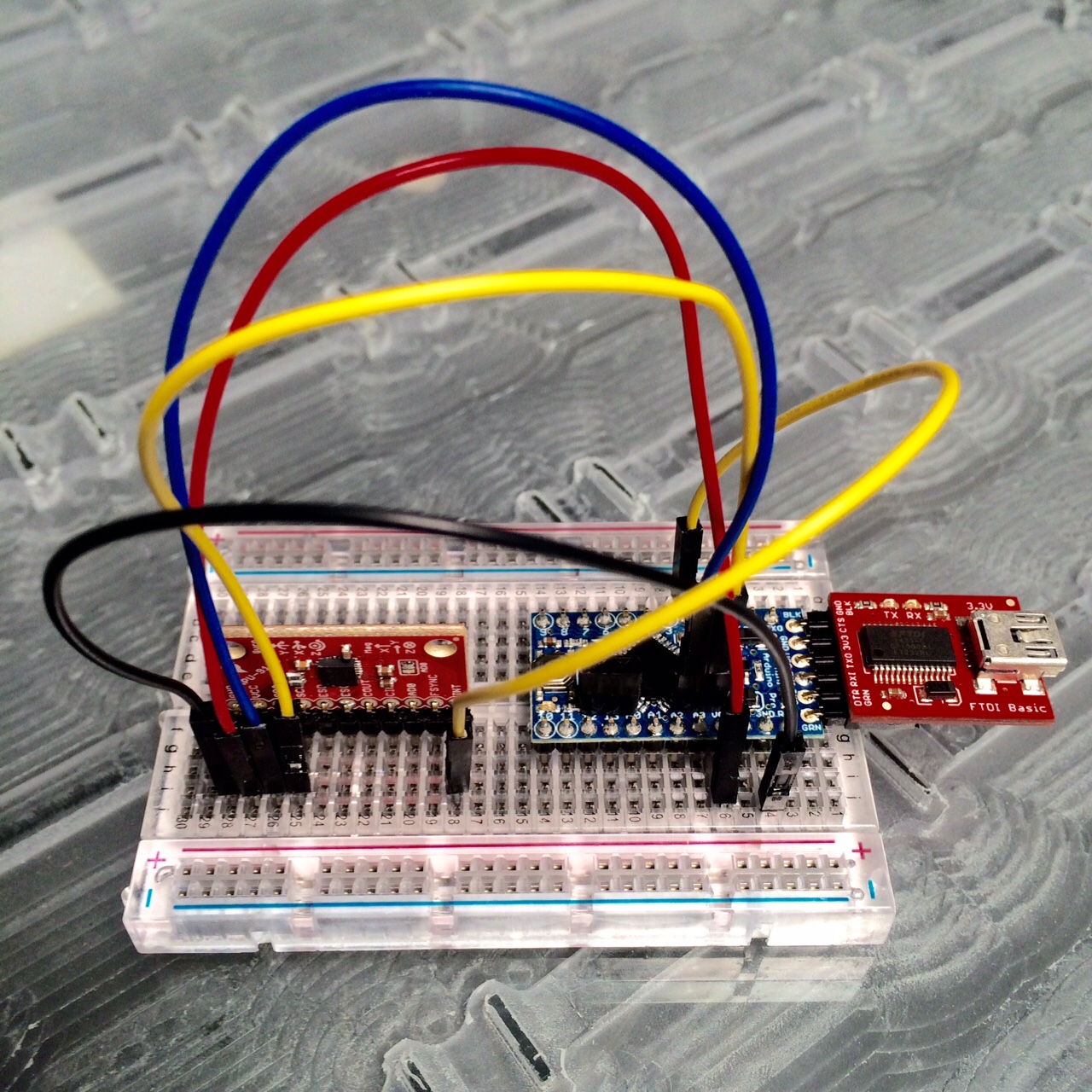
Make connections to the breakout anyway that makes you happy. The board in the above photo has a right angle header soldered to it. We could have used a straight header, or wire, etc. Please note that different mounting orientations will alter the orientation of the axes. Make sure your code matches the physical orientation for your projects.
For this demo, we made the following connections:
| Arduino Pro Mini | MPU‑9150 Breakout | Notes |
|---|---|---|
| VCC | VCC | +3.3V |
| GND | GND | +0V |
| SDA | SDA | Serial data @ +3.3V CMOS logic |
| SCL | SCL | Serial clock @ +3.3V CMOS logic |
| D2 | INT | INT0 on Arduino | Interrupt output "totem pole or open-drain" on MPU-9150 |
The whole system in our testing was powered via USB through the FTDI basic.
