MIDI Tutorial
 Byron J.
Advanced Messages
Polyphonic Pressure (0xA0) and Channel Pressure (0xD0)
Some MIDI controllers include a feature known as Aftertouch. While a key is being held down, the player can press harder on the key. The controller measures this, and converts it into MIDI messages.
Aftertouch comes in two flavors, with two different status messages.
The first flavor is polyphonic aftertouch, where every key on the controller is capable of sending its own independent pressure information. The messages are of the following format:
- n is the status (0xA)
- c is the channel nybble
- kk is the key number (0 to 127)
- pp is the pressure value (0 to 127)
Polyphonic aftertouch is an uncommon feature, usually found on premium quality instruments, because every key requires a separate pressure sensor, plus the circuitry to read them all.
Much more commonly found is channel aftertouch . Instead of needing a discrete sensor per key, it uses a single, larger sensor to measure pressure on all of the keys as a group. The messages omit the key number, leaving a two-byte format
- n is the status (0xD)
- c is the channel number
- pp is the pressure value (0 to 127)
Pitch Bend (0xE0)
Many keyboards have a wheel or lever towards the left of the keys for pitch bend control. This control is usually spring-loaded, so it snaps back to the center of it's range when released. This allows for both upward and downward bends.
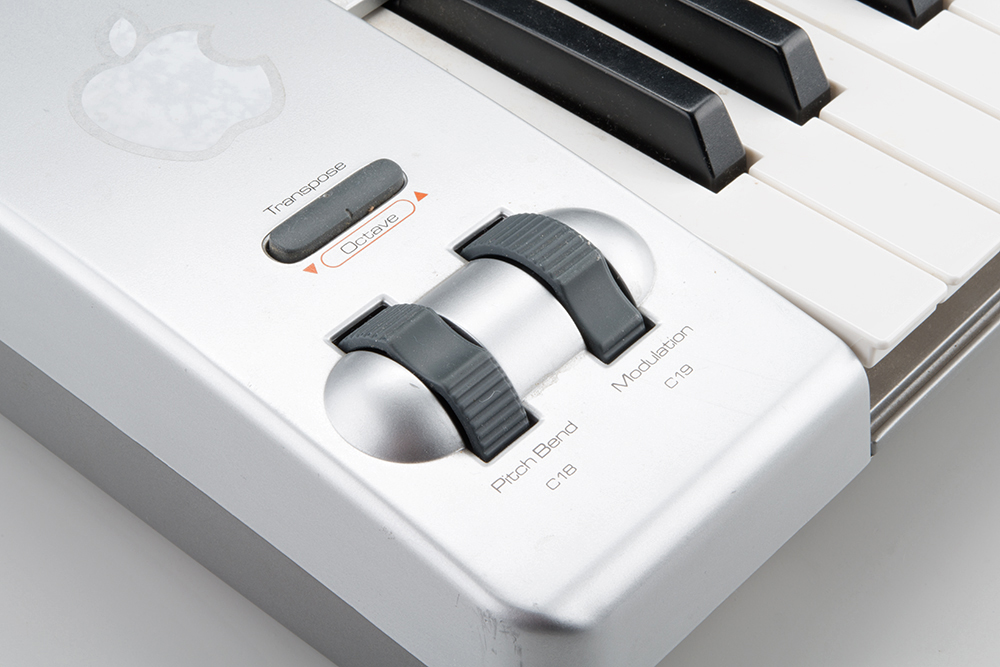
The wheel sends pitch bend messages, of the format
- n is the status (0xE)
- c is the channel number
- LL is the 7 least-significant bits of the value
- MM is the 7 most-significant bits of the value
You'll notice that the bender data is actually 14 bits long, transmitted as two 7-bit data bytes. This means that the recipient needs to reassemble those bytes using binary manipulation. 14 bits results in an overall range of 214, or 0 to 16,383. Because it defaults to the center of the range, the default value for the bender is halfway through that range, at 8192 (0x2000).
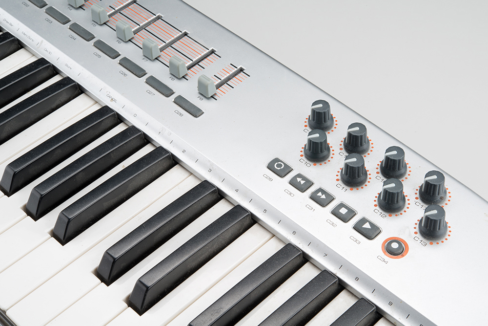
Control Change (0xB0)
In addition to pitch bend, MIDI has provisions for a wider range of expressive controls, sometimes known as continuous controllers, often abbreviated CC. These are transmitted by the remaining knobs and sliders on the keyboard controller shown below.
These controls send the following message format:
- n is the status (0xB)
- c is the MIDI channel
- cc is the controller number (0-127)
- vv is the controller value (0-127)
Each of the controllers in the picture above is configured to send a different controller number.
Typically, the wheel next to the bender sends controller number one, assigned to modulation (or vibrato) depth. It is implemented by most instruments.
The remaining controller number assignments are another point of confusion. The MIDI specification was revised in version 2.0 to assign uses for many of the controllers, as shown on pages 2 and 3 of this document. However, this implementation is not universal, and there are ranges of unassigned controllers.
On many modern MIDI devices, the controllers are assignable. On the controller keyboard shown in the photos, the various controls can be configured to transmit different controller numbers. The flip-side is also often true -- controller numbers can be mapped to particular parameters. Virtual synthesizers frequently allow the user to assign CCs to the on-screen controls. This is very flexible, but it might require configuration on both ends of the link and completely bypasses the assignments in the standard.
Program Change (0xC0)
Most synthesizers have patch storage memory, and can be told to change patches using the following command:
- n is the status (0xc)
- c is the channel
- pp is the patch number (0-127)
This allows for 128 sounds to be selected, but modern instruments contain many more than 128 patches. Controller #0 is used as an additional layer of addressing, interpreted as a "bank select" command. Selecting a sound on such an instrument might involve two messages: a bank select controller message, then a program change.
System Messages (0xF0)
The final status nybble is a "catch all" for data that doesn't fit the other statuses. They all use the most significant nybble of 0xF, with the least significant nybble indicating the specific category.
We covered system realtime messages in the previous section. The messages are denoted when the MSB of the second nybble is 1. When that bit is a 0, the messages fall into two other subcategories.
System Common
If the MSB of the second second nybble is not set, this indicates a System Common message. Most of these are messages that include some additional data bytes.
| System Common Messages | |||||
| Type | Status Byte | Number of Data Bytes | Usage | ||
| Time Code Quarter Frame | 0xF1 | 1 | Indicates timing using absolute time code, primarily for synthronization with video playback systems. A single location requires eight messages to send the location in an encoded hours:minutes:seconds:frames format*. | ||
| Song Position | 0xF2 | 2 | Instructs a sequencer to jump to a new position in the song. The data bytes form a 14-bit value that expresses the location as the number of sixteenth notes from the start of the song. | ||
| Song Select | 0xF3 | 1 | Instructs a sequencer to select a new song. The data byte indicates the song. | ||
| Undefined | 0xF4 | 0 | |||
| Undefined | 0xF5 | 0 | |||
| Tune Request | 0xF6 | 0 | Requests that the reciever retune itself**. | ||
**While modern digital instruments are good at staying in tune, older analog synthesizers were prone to tuning drift. Some analog synthesizers had an automatic tuning operation that could be initiated with this command.
System Exclusive
If you've been keeping track, you'll notice there are two status bytes not yet defined: 0xf0 and 0xf7.These are used by the System Exclusive message, often abbreviated at SysEx. SysEx provides a path to send arbitrary data over a MIDI connection. There is a group of predefined messages for complex data, like fine grained control of MIDI Time code machinery. SysEx is also used to send manufacturer defined data, such as patches, or even firmware updates.
System Exclusive messages are longer than other MIDI messages, and can be any length. The messages are of the following format:
The message is bookended with distinct bytes.
- It opens with the Start Of Exclusive (SOX) data byte, 0xF0.
- The next one to three bytes after the start are an identifier.
- Values from 0x01 to 0x7C are one-byte vendor IDs, assigned to manufacturers who were involved with MIDI at the beginning.
- If the ID is 0x00, it's a three-byte vendor ID - the next two bytes of the message are the value.
- ID 0x7D is a placeholder for non-commercial entities.
- ID 0x7E indicates a predefined Non-realtime SysEx message.
- ID 0x7F indicates a predefined Realtime SysEx message.
- After the ID is the data payload, sent as a stream of bytes.
- The transfer concludes with the End of Exclusive (EOX) byte, 0xF7.
The payload data must follow the guidelines for MIDI data bytes -- the MSB must not be set, so only 7 bits per byte are actually usable. If the MSB is set, it falls into three possible scenarios.
- An End of Exclusive byte marks the ordinary termination of the SysEx transfer.
- System Real Time messages may occur within the transfer without interrupting it. The recipient should handle them independently of the SysEx transfer.
- Other status bytes implicitly terminate the SysEx transfer and signal the start of new messages.
Troubleshooting Tip: Some inexpensive USB-to-MIDI interfaces aren't capable of handling messages longer than four bytes. If you're having trouble with SysEx transfers when using such an interface, it might be useful to inspect the messages on the bus with an application like MIDI Ox.
Implementation chart
With all of these different messages, MIDI has become somewhat dialectic -- not every unit implements every message. A simple controller-to-synthesizer link might only need to use note on and off messages, while an on-stage pyrotechnic controller might completely ignore note messages, requiring time code, and specific SysEx commands to arm the smokebombs and flashpots.
To help the user understand what messages a specific device uses, the manual often includes a table that indicates what it can send and receive.
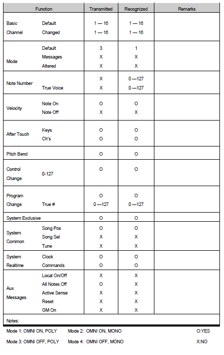
The chart above shows a typical implementation chart for an instrument. It tells us some notable things about the MIDI dialect spoken by this device:
- This device transmits Note On velocity, but not note Off velocity.
- It also uses polyphonic and/or channel aftertouch (you can select which in a configuration menu).