MicroView Hookup Guide
 Joel_E_B, Marcus Schappi
OLED Memory Map
This section goes into more detail about how the OLED screen functions and how the MicroView library works with the screen's controller. Read on to get a better understanding of how the MicroView prints and draws to the OLED screen.
The SSD1306 is the controller built into the MicroView’s OLED display. It has flexible yet complex segment and common drivers. Vast knowledge on memory addressing is required in order to use the SSD1306 controller.
MicroView’s library was written to hide away the complexities of the SSD1306 controller so that users can issue simple commands to control the display. Although the SSD1306 has a built-in RAM (memory) for the screen, when connected using the SPI method, the ATmega328P is not able to read the RAM (memory) of the SSD1306. Therefore, the software will not be able to manipulate the screen buffer to perform mathematical operations.
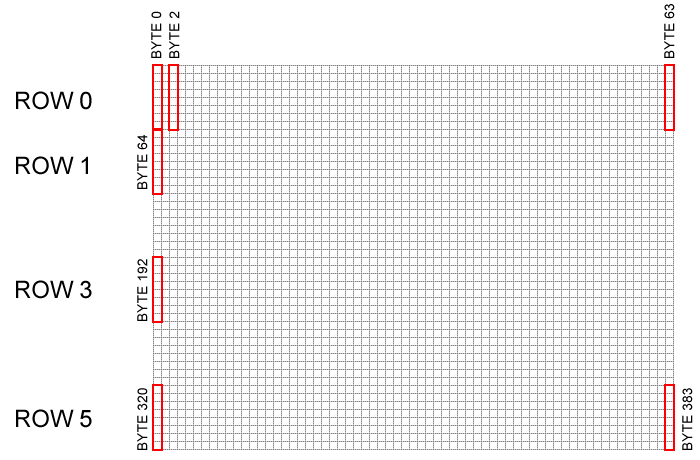
MicroView’s library overcomes this by allocating 384 bytes ( (64x48)/8 bits) of memory from ATmega328P as buffer. The library can now manipulate the screen buffer and then perform a bulk transfer from the ATmega328P’s memory to the internal memory of the SSD1306 controller.
The 384 bytes of screen buffer are declared in MicroView’s library as
language:c
static uint8_t screenmemory [] = {.total 384 bytes of data..};
and are arranged in a linear form representing the following 64x48 pixel coordinate system.
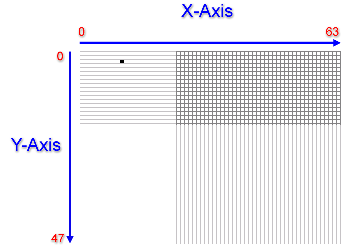
Based on the above illustration, for example, if a user wished to plot a pixel at the position of the black dot, where X=10 and Y=2, the user would issue the following command:
language:c
uView.pixel(10,2);
This command would then calculate the exact location of the screen buffer and set a BIT in the corresponding BYTE to the X,Y position.
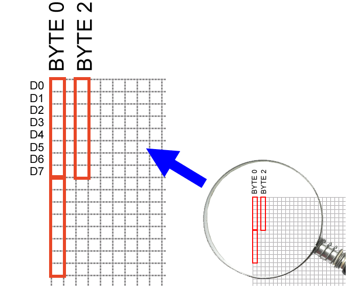
Based on the above illustration, a pixel turned on at X=2 and Y=3 means BYTE 2 of the screen buffer has data of 0x08 (hex).
Two pixels at X=2,Y=3 and X=2,Y=2 turned on means BYTE 2 of the screen buffer has data of 0x0c (hex).
The following C code shows a pixel-by-pixel way to draw a straight line of 5 pixels starting from 10,2 to 10,6.
language:c
uView.pixel(10,2);
uView.pixel(10,3);
uView.pixel(10,4);
uView.pixel(10,5);
uView.pixel(10,6);
The MicroView library allows you to draw lines by specifying the start and end coordinates. The above line could be drawn with this simple one-line command:
language:c
uView.line(10,2,10,6);
In order for the library to perform extremely fast mathematical operations on the screen buffer (more than 100 frames per second), calls to the drawing functions within the MicroView library do not immediately transfer the contents of screen buffer to the SSD1306 controller. A display() command is required to instruct the library to perform the bulk transfer from the screen buffer to the SSD1306 controller:
language:c
uView.display();
This function takes the whole screen buffer in the ATmega328P and transfers it (via SPI bus, programmed at 8Mhz) to the internal memory of the SSD1306. As soon as the memory is being transferred, the pixels corresponding to the screen buffer will show up on the OLED display.