microSD Sniffer Hookup Guide
 Toni_K
 Introduction
The microSD Sniffer is a useful tool for hacking or debugging circuits with microSD functionality.
The Sniffer allows you to see the SPI signals passing back and forth from your microSD card to your microcontroller or project.
Covered in This Tutorial
This tutorial will show you how to setup the sniffer as well as how to use it to "sniff" the data transmitted to and received from a microSD card.
Materials Required
To follow along with this tutorial, we recommend you have access to the following materials.
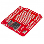
You will also need a project that has a microSD slot involved. We will be using the microSD Shield and Redboard.

You will also need some kind of logic analyzer. You can use anything like the following:
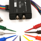
USB Oscilloscope - MSO-19
TOL-09263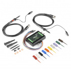
USB Oscilloscope - MSO-28
TOL-11219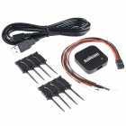
Logic 4 - USB Logic Analyzer
TOL-13195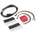
Logic Pro 8 - USB Logic Analyzer
TOL-13196Suggested Reading
If you aren't familiar with the following concepts, we recommend reviewing them before beginning to work with the microSD Sniffer.
Hardware Overview
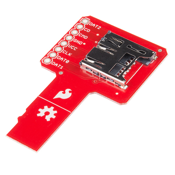
Hardware wise, the microSD Sniffer is pretty simple and straight-forward! There's only 3 main parts you need to be aware of.
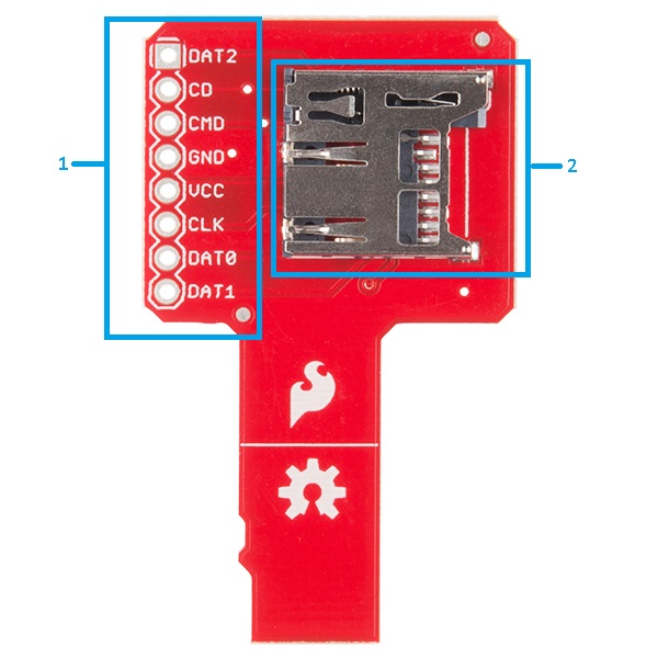
1. Headers
The pins of the SD card are broken out for a standard 0.1-inch row of header holes. This allows you to solder headers onto the board and connect into a breadboard for prototyping. Alternatively, you can also just connect IC hooks on these holes and use a logic analyzer or oscilloscope to monitor the traffic across the SPI bus.
2. microSD Socket
This is your standard microSD socket. It fits microSD cards. Hurray simplicity!
3. microSD Insert
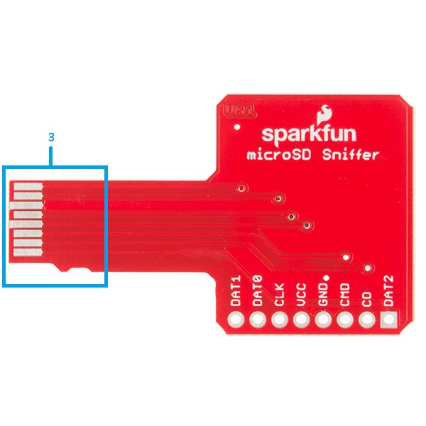
These are the actual connection pins for the microSD Sniffer. You will plug these into your circuit in place of where you would normally plug in a microSD card. Notice how they look exactly like the bottom of your microSD card?
Hardware Hookup
Assembly
We'll be using the microSD Sniffer to see the SPI traffic between the microSD shield and the microSD card. If you aren't sure how to set up the microSD shield, please review our tutorial here.
Insert the microSD card into the microSD Sniffer socket, and plug the end of the microSD Sniffer into the socket on the microSD shield.
Everything is now ready to go, but we still need something to actually watch the traffic. For this, we will be using the Logic 4 - USB Logic Analyzer. You can use whatever analyzer you have around, but you will need one with 8 channels.
Pair one channel from the analyzer to one header on the microSD Sniffer. Repeat this until all of your headers have been connected to the analyzer. Keep in mind that your analyzer may have a dedicated GND line or other dedicated channels, so make sure you match any of those up if that's the case.
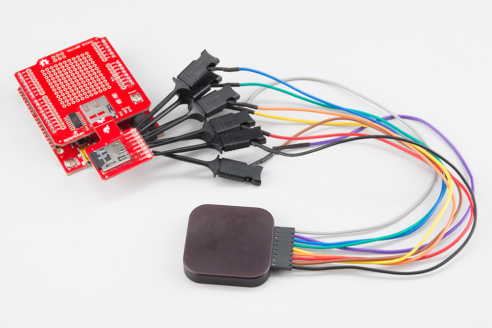
Once everything is connected, it's time to power it all up and watch the SPI traffic!
Functionality
Visualization
We can now view the data on the SPI bus with the logic analyzer. In our example, the Redboard is running the Examples>SD>Datalogger.ino sketch included by default in the Arduino IDE.
Open up the logic analyzer software, and configure it for your set up. In our example, we've labeled each channel with the corresponding pin name on the microSD Sniffer.
The analyzer collects 1 million samples at 8MHz. Once it has collected data, you should see something similar to the following.
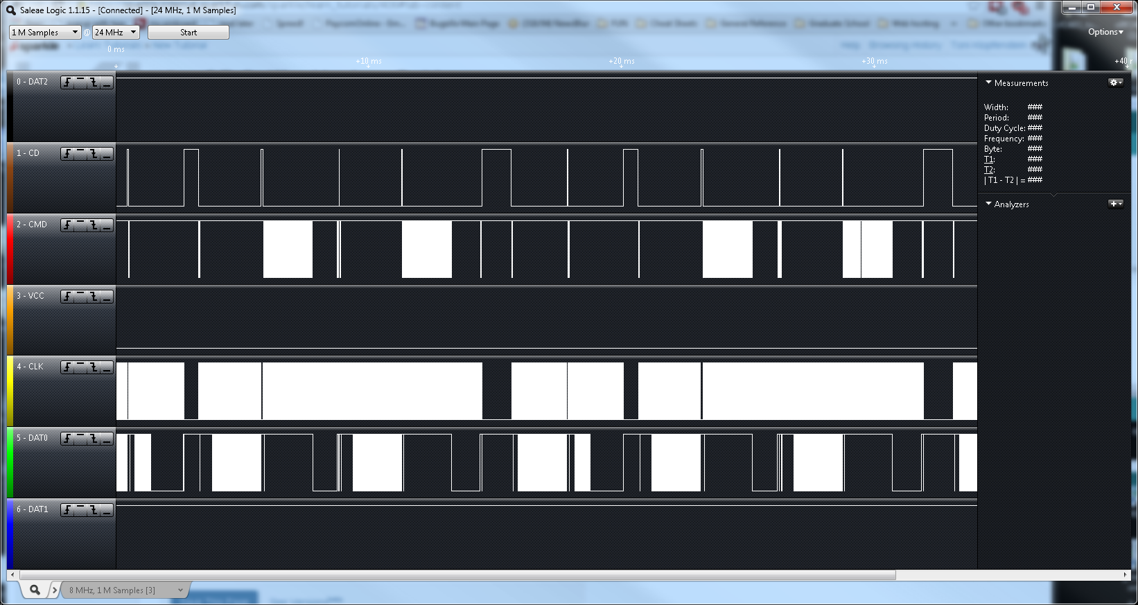
We can see there is definitely something occuring on several of the lines, but it's still not clear what. If we look at our time scale, the range shown is 0ms to ~35ms. We can zoom in on a smaller time scale to get more detail about the communication occurring.
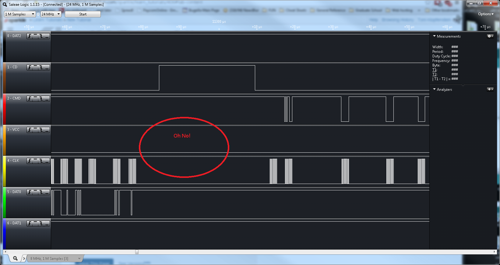
Looking at our data, we can see something is not quite right -- according to the VCC line, there's no power going to our system! While the issue in this case was only due to a loose connection between the IC hook on the analyzer and the Sniffer, you could dig deeper into each signal to debug your circuit if there is a problem. If we fix the loose connection, the data looks better, showing a HIGH signal on VCC.
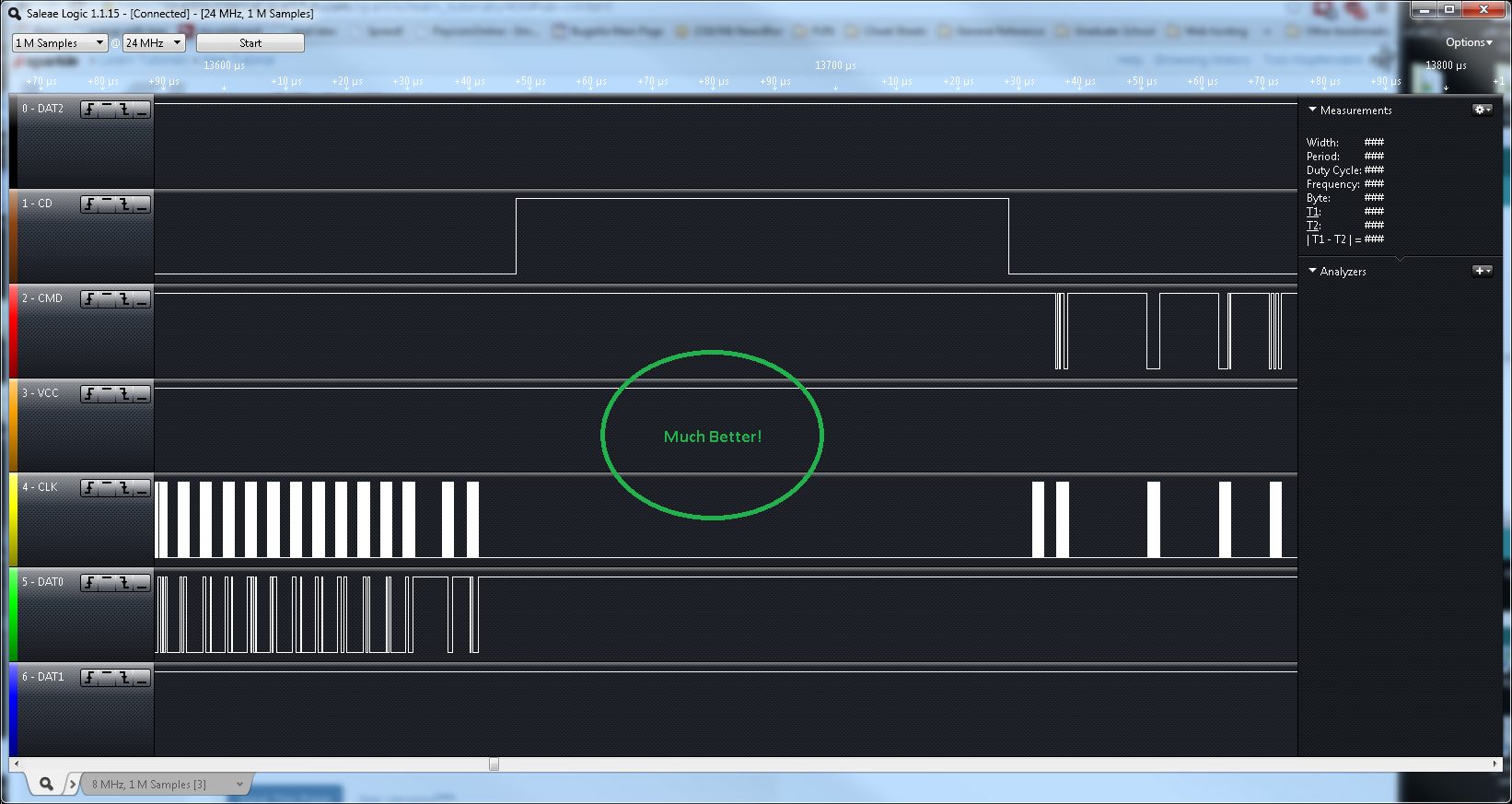
Again, this is a very simplified example, but you could use the Sniffer to verify the clock signal to your card, or to see if there are actual data signals being sent to the microSD card.
Resources and Going Further
Going Further
Now that you've successfully worked with your microSD Sniffer, you can use this to debug any project that uses microSD cards, or hack the communication protocol between system and SD card.
If you have any feedback, please visit the comments or contact our technical support team at TechSupport@sparkfun.com.
Additional Resources
Check out these additional resources for more information and other project ideas.