Logomatic Hookup Guide
 Toni_K
 Logging Isn't Just for Lumberjacks
The Logomatic is a data logger that allows you to log analog or serial data from your project. It logs to a microSD card and is compatible with high capacity cards. The board can be plugged in via microUSB and mounts as a universal mass storage device.

Suggested Reading
If you are not familiar with any of the following concepts, you may want to review them before moving ahead with the Logomatic.
Serial Communication
Battery Technologies
How to Power a Project
Working with Wire
Using GitHub to Share with SparkFun
Serial Terminal Basics
Hardware Overview
Power
The Logomatic has a very useful power circuitry. There is an on-board power switch, enabling the user to turn off the board to save power as needed. The board also comes with a JST connector for a LiPo battery to be connected to the board. While there is a battery plugged into the board, and the board is connected via USB, the battery will also be charged. You do not need to have the board turned on to charge the battery.
There is also an low dropout 3.3V regulator on the board. The maximum power dissipation of the voltage regulator is about 450 mW, and the maximum current draw of the Logomatic is about 80 mA. This puts the maximum voltage of the Logomatic at (450mW)/(80mA) + 3.3V = 8.925V. However, this will almost put the voltage regulator into thermal shutdown. To prevent this, the supply voltage should be kept between 3.6V and 7.5V.
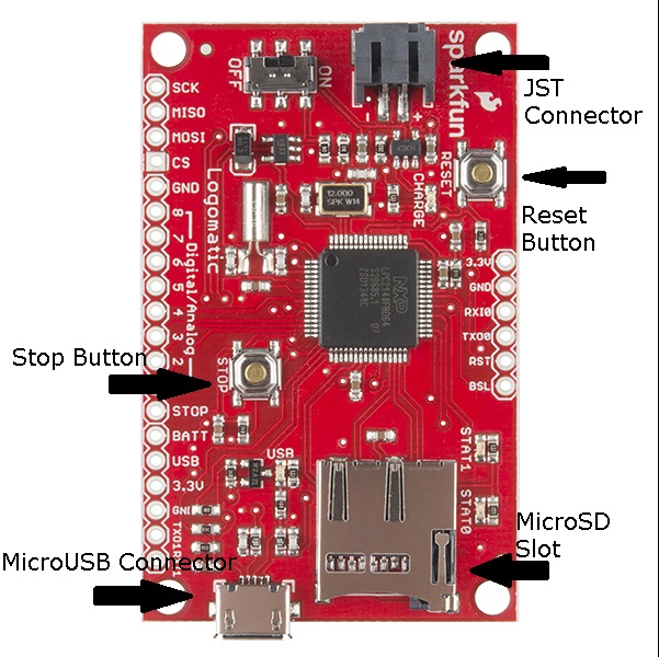
Micro-B USB Connector


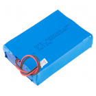

Lithium Ion Battery - 1Ah
PRT-13813The microSD card can be accessed over USB. When connected to a computer using a microUSB cable, the Logomatic will mount as a new drive. This will appear just like a standard flash drive would once the board is turned on. Once it is mounted, you can create, delete, or edit files. To remove it, simply turn off the board, and disconnect the USB cable.
Stop Button
The stop button will halt the Logomatic. All logging will stop, and any partially-filled buffer will be automatically logged to the microSD card. Turning off the Logomatic or removing its power source will also stop the unit from logging (and keep the log file intact), but, if there is a partially filled buffer, it will not be logged. When the unit is stopped with the stop button, the LEDs will blink continuously until the unit is power-cycled.
Logging Configuration
First Time Power-Up
Initializing the Configuration and Log Files
Before powering up your Logomatic for the first time, insert your microSD card into a card reader, and make sure to format it for FAT32. Insert the card into your Logomatic, insert a LiPo battery into the two pin JST connector, and turn the power switch to the ON position. The STAT0 and STAT1 LEDs will blink reassuringly then go quiet.
Mounting as a USB Drive
Turn the unit off, plug a USB (connector type micro-B) into the unit, and power back on with the power switch. The unit will mount as a drive on your computer (alternatively, you can remove the card and use a card reader to read it). You will now find two files on your card, LOGCON.TXT and LOG0.TXT. The first file is the configuration file, and the second is the first logged file (empty). Open up the configuration file in a text editor and you will see this default configuration:
MODE = 0
ASCII = Y
Baud = 4
Frequency = 100
Trigger Character = $
Text Frame = 100
AD1.3 = N
AD0.3 = N
AD0.2 = N
AD0.1 = N
AD1.2 = N
AD0.4 = N
AD1.7 = N
AD1.6 = N
Safety On = Y
Configuring LOGCON.TXT File
The LOGCON.TXT allows you to control how the Logomatic records data to the memory card. Let's go over the different settings.
Mode
There are 3 mode settings:
"Mode = 0" (Automatic UART Logging) - Logs everything that comes in on UART0, provided that it's the right UART configuration (8 data bits, one stop bit, no parity, data rate of your choosing).
"Mode = 1" (Triggered UART Logging) - Logs a specified number of characters ("Text Frame = 100" in this case will result in 99 characters logged after the trigger) after a specified character ("Trigger = $" in this case).
"Mode = 2" (ADC Logging) - Logs ADC measurements according to which are selected as active (see below) at whatever frequency is specified ("Frequency = 100" in this case).
ASCII
The "ASCII" field only applies to ADC mode (Mode "2"). It specifies whether the unit will log in these formats:
- "ASCII = Y"- ASCII
- "ASCII = N" - binary
Baud
The "Baud" field sets the baud rate for the UART logging modes. The available rates are as follows:
"1" = 1200
"2" = 2400
"3" = 4800
"4" = 9600
"5" = 19200
"6" = 38400
"7" = 57600
"8" = 115200
Frequency
The "Frequency" field only applies to ADC logging mode and is responsible for setting the sampling rate of the Logomatic. The number shown (100 in this case) is in Hertz and can be set from 1 to 9999. However, if the frequency safeties are active, the maximum values will be imposed as indicated in the Safety On section.
MODE = 2
ASCII = Y
Baud = 4
Frequency = 01
.
.
.
Trigger Character
The "Trigger Character" field only applies to the triggered UART mode (Mode 1). This is the character that the device waits for to begin logging a specified number of characters.
Text Frame
The "Text Frame" field specifies the number of characters to be logged with the trigger character when the Logomatic is running in Mode 1. The reader should be aware that the first character in the logged text frame will be the trigger character, so if you wish to log 100 characters after the trigger you should set the text frame to 101.
Each text frame is delimited with a carriage return and a line feed character, so the maximum text frame size is 510 bytes. If this number is exceeded, it will be automatically reset to 510.
Operational ADC Lines
The next eight lines in the configuration file indicate which ADC lines are to be read by the Logomatic. They can each be turned on by changing the "N" to a "Y". These values have no affect when the Logomatic is in one of the two UART modes.
The ADC values in the configuration files correspond to the outputs on the board as follows:
| LPC2148 Microcontroller Pin Assignment | Logomatic Digital/Analog Silkscreen Pin Number |
|---|---|
| AD1.3 | 8 |
| AD0.3 | 1 |
| AD0.2 | 2 |
| AD0.1 | 3 |
| AD1.2 | 7 |
| AD0.4 | 4 |
| AD1.7 | 5 |
| AD1.6 | 6 |
Safety On
The last field in the configuration file is the "Safety On" field. This sets the frequency caps for ADC mode on with a "Y" or off with an "N". The frequency caps are as follows:
1 channel active, 1500 Hz maximum
2 channels active, 750 Hz maximum
3 channels active, 500 Hz maximum
4 channels active, 375 Hz maximum
5 channels active, 300 Hz maximum
6 channels active, 250 Hz maximum
7 channels active, 214 Hz maximum
8 channels active, 187 Hz maximum
There is also a hardware test function that can be accessed through this parameter. Instead of a "Y" or an "N", setting it to "T" will put the unit in hardware test mode, where you can watch the ADC lines slowly polled over the serial UART lines at 9600 baud. Note: this mode is not intended for normal operation. It is only intended for determining hardware failures.
Example Output Formats
The formats of the text files produced by the Logomatic will be a little different in each mode depending on the configurations explained above. Here are a few possible configurations:
For mode 0 (automatic UART), Any ASCII characters that come in on the UART will be sent to the microSD card. Nothing is omitted and nothing is added.
For mode 1 (triggered UART), anything after and including the trigger character will be logged, including white space characters, up to the end of the specified data frame. Each data frame is delimited with a carriage return and a line feed character to make it easier to distinguish between the frames.
In ASCII ADC mode (mode 2, ASCII = Y), each single measurement is between 1 and 4 characters in length depending on how many digits are required, followed by a tab (ASCII 9) for delimiting. At the end of each measurement frame, that is, one time through the list of selected active ADC lines, carriage return and line feed characters are placed for further delimiting. The sequence of measurements displayed in the file from left to right are exactly the sequence of channels selected in the configuration file from to to bottom.
In binary ADC mode (mode 2, ASCII = N), each measurement is two bytes in length (MSB, LSB), and they will occur in the same sequence as the ASCII logs with respect to the configuration file. There are no delimiters between measurements, but measurement frames are delimited by the characters "$$".
Hardware Hookup
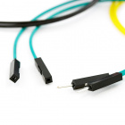
It's now time to hook up your Logomatic to your system of choice for logging. For our example, we will be hooking the Logomatic up to an analog temperature sensor, the TMP36 and some jumper wires. Make sure to solder header pins of your choice to the Logomatic for a secure connection. We will be logging the temperature readings to our microSD card.
Required Materials
To follow along with this example, you will need the following materials. You may not need everything though depending on what you have and your setup. Add it to your cart, read through the guide, and adjust the cart as necessary.


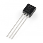
Temperature Sensor - TMP36
SEN-10988
Circuit Diagram
Below is a diagram of connecting an analog temperature sensor to one of the Logomatic's ADC pins.
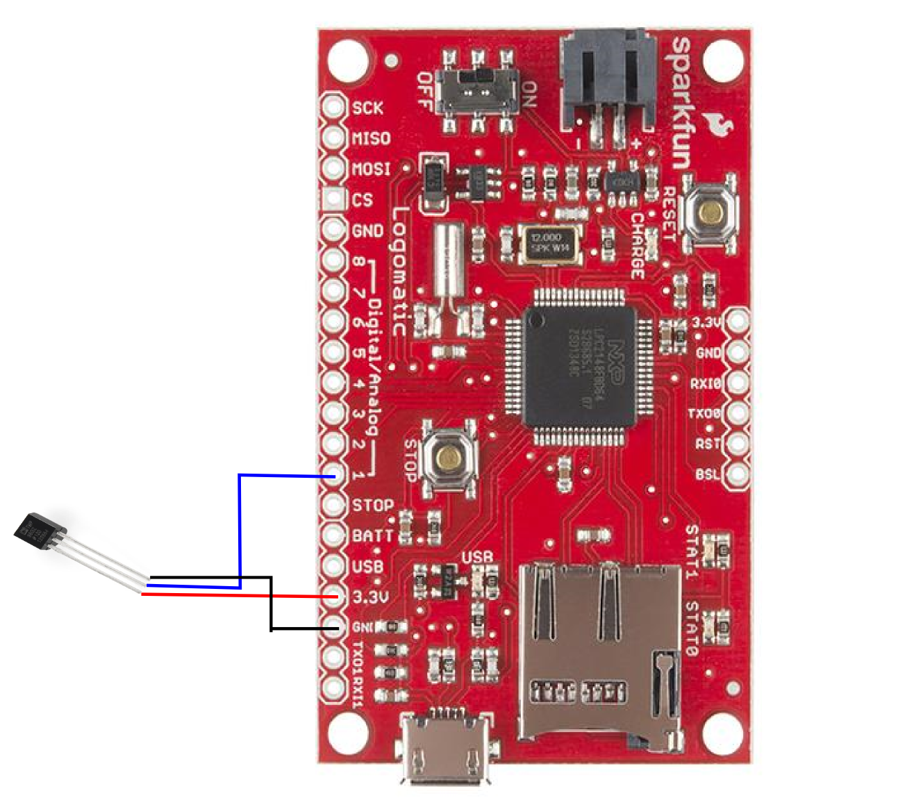
The connections above are as follows:
TMP36 → Logomatic
VCC → 3.3V
Signal → A0
GND → GND
Operation
Now that you know how the Logomatic works and have it connected, it's time to power it up. Set your configuration however you like. In this example, we'll set the configuration file to read temperature on analog pin 1 at a rate of 100Hz and log the raw analog values in ASCII format like so:
MODE = 2
ASCII = Y
Baud = 4
Frequency = 100
Trigger Character = $
Text Frame = 100
AD1.3 = N
AD0.3 = Y
AD0.2 = N
AD0.1 = N
AD1.2 = N
AD0.4 = N
AD1.7 = N
AD1.6 = N
Saftey On = Y
Make sure the microSD card is fully inserted in the microSD slot with a LiPo battery and turn the switch to the ON position to begin logging! The two status LEDs will blink at you rather quickly during the initialization, then the unit will go to work with the settings you chose. The only further indication of operation that you will see is when one of the two data buffers logs to the SD card, STAT0 for buffer # 1 and STAT1 for buffer # 2. These will be very quick "blips" because the LEDs are only on during the write process, between 20-40ms.
When you are done logging, press the STOP button before shutting off the unit to be sure that any unfilled buffers are logged to the SD card and all the interrupts are disabled.
The Logomatic will create up to 256 log files in text format, numbering from LOG0.TXT to LOG255.TXT. The most recent log file will be the one with the highest number.
Resources and Going Further
Now that you've successfully gotten your Logomatic logging away, you can start tweaking the system to your exact preferences. The firmware is open-source and available here, or you can check GitHub repository for the most current version. Feel free to tweak or change the firmware. The unit's code can be changed via the USB bootloader. You can also reprogram the unit via and LPC programmer. For more information about reprogramming the Logomatic via the bootloader, check out the LPC2148 USB Bootloader tutorial.
For more information, check out the resources below:
Check out these additional resources for more information and other project ideas.
- Sunny Buddy Solar Charger Hook-Up Guide
- Weather Shield Hook-Up Guide
- HTU21D Humidity Sensor Hook-Up Guide
If you have any feedback, please visit the comments or contact our technical support team at TechSupport@sparkfun.com.