MicroMod WiFi Function Board - ESP32 Hookup Guide
Hardware Hookup
If you have not already, make sure to check out the Getting Started with MicroMod: Hardware Hookup for information on inserting your Processor and Function Boards to the Main Board.
Getting Started with MicroMod
Adding a Function Board to the Main Board
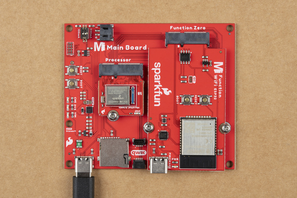
We'll assume that you have inserted a Processor Board into the Main Board already. The process is the same for adding a Function Board. The only difference is that you will be adding two screws to hold the Function board down.
Align the Function Board's key into its M.2 connector's socket. Insert the board at an angle (~25°), push down, and tighten one of the screw to hold the board down. Attach the second screw on the other side of the board. Once the board is aligned, tighten both screws fully to secure the board. In this case, we had the WiFi Function Board secured in the M.2 connector socket. Depending on your application, you may have a different Function Board.
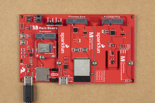
If you decide to have two function boards attached to the Main Board - Double, we recommend tightening the screw between the two Function Boards first to hold them down before attaching the remaining screws on either side of the Function Boards. In this case, we had the WiFi Function Board and the Environmental Function Board secured in the M.2 connector socket. Depending on your application, you may have different function boards.
ESP32 Firmware Update
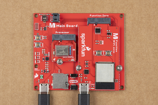
To update the firmware you will need to connect the USB C cable to the MicroMod WiFi Function Board (ESP32) to a computer's COM port. An additional Main Board with a second USB C cable is also needed to power the Main Board and MicroMod WiFi Function Board.


