$18.95
With the MicroMod specification, we shrunk down the PCB size for the SAMD51 32-bit ARM Cortex-M4F MCU! This tutorial covers the basic functionality of the MicroMod SAMD51 and highlights its features.
To follow along with this tutorial, you will need the following materials. You may not need everything though depending on what you have. Add it to your cart, read through the guide, and adjust the cart as necessary.
If you aren't familiar with the MicroMod ecosystem, we recommend reading here for an overview.
| MicroMod Ecosystem |
If you aren’t familiar with the following concepts, we also recommend checking out these tutorials before continuing.
All of our MicroMod Processor Boards come equipped with the M.2 MicroMod Connector, which leverages the M.2 standard and specification to allow you to install your MicroMod Processor Board on your choice of carrier board. Most of the pins use a common pinout to ensure cross platform compatibility.
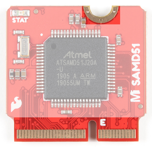
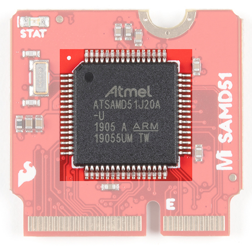
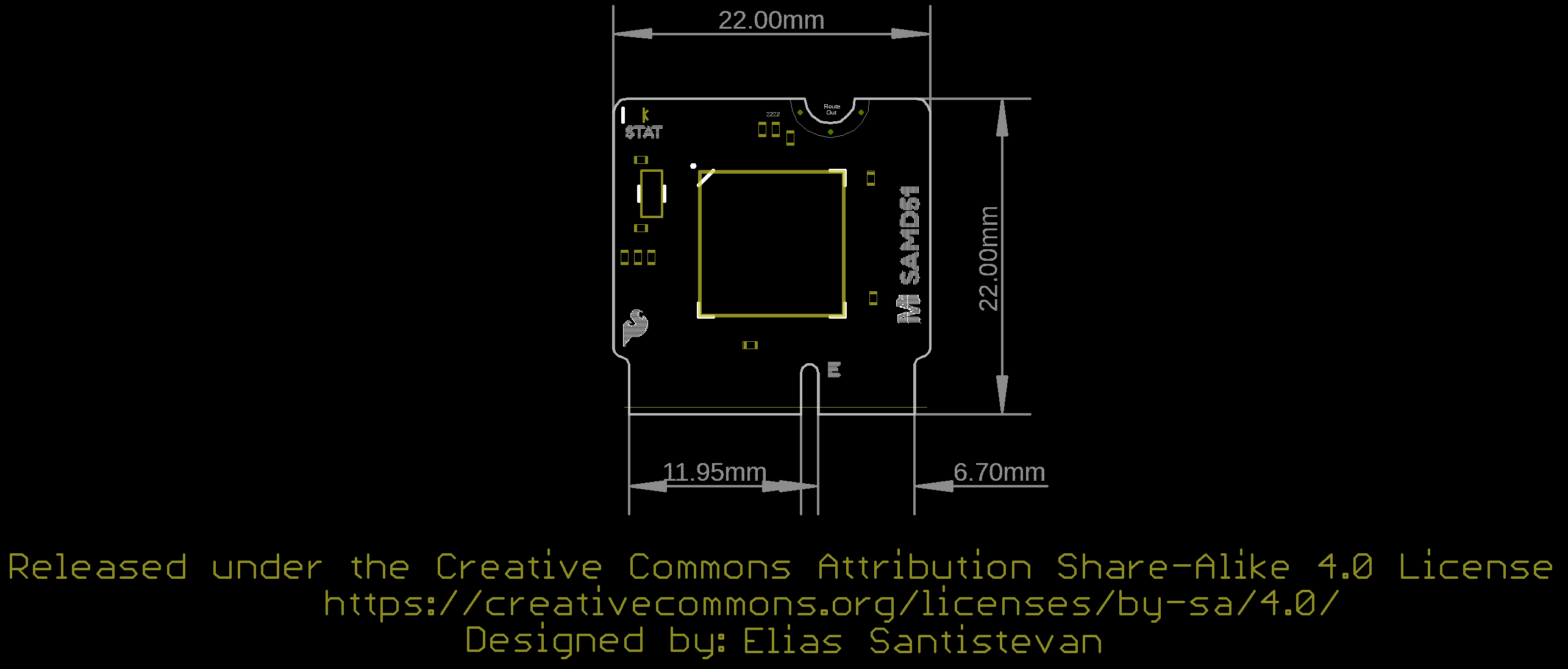
The brains of the processor board is the ATSAMD51J20 32-bit ARM Cortex M4 processor. An external 32.768kHz crystal is used as the clock for the ATSAMD51. However, the MCU itself has a maximum CPU speed of 120MHz. The SAMD51 should be powered with 3.3V from a carrier board's M.2 connector. The logic levels for the I/O pins are 3.3V.
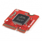
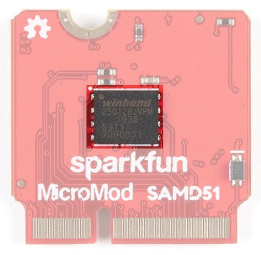
On the back of the board is the W25Q128JVPIM, which adds 128Mb (16MB) of flash memory externally. This is connected to the SAMD51's SPI1 port, which is not broken out on the card's edge.
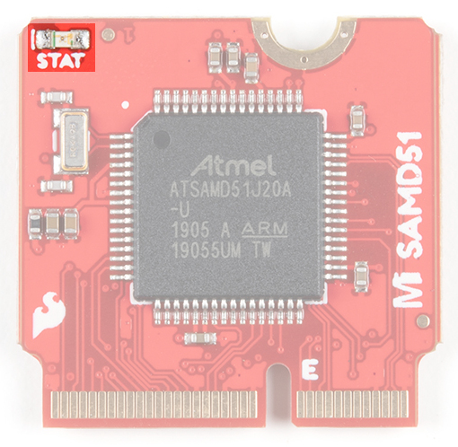
A STAT LED is added to the top side of the board. This is useful debugging or as a status indicator. Additionally, you can use this to determine if the board is in bootloader mode. Pressing the reset button twice will put the board into bootloader mode causing the LED to fade in/out. This is connected to pin 13.
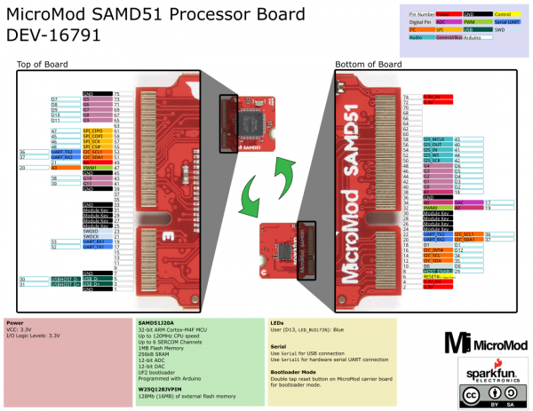
The complete pin map can be found in the table below or you can refer to the schematic.
| AUDIO | UART | GPIO/BUS | I2C | SDIO | SPI | Dedicated |
| SAMD51 Pin |
Alternate Function |
Primary Function |
Bottom Pin |
Top Pin |
Primary Function |
Alternate Function |
SAMD51 Pin |
|---|---|---|---|---|---|---|---|
| (Not Connected) | 75 | GND | |||||
| D14 | 3.3V_IN | 74 | 73 | G5 | D7 | ||
| 3.3V | 72 | 71 | G6 | D8 | |||
| - | 70 | 69 | G7 | D9 | |||
| - | 68 | 67 | G8 | D10 | |||
| - | 66 | 65 | G9 | D11 | |||
| - | 64 | 63 | - | ||||
| - | 62 | 61 | SPI_CIPO | 47 | |||
| - | 60 | 59 | SPI_COPI | 45 | |||
| 43 | I2S_MCLK | 58 | 57 | SPI_SCK | 46 | ||
| 40 | I2S_SDO | 56 | 55 | SPI_CS | 48 | ||
| 41 | I2S_SDI | 54 | 53 | I2C_SCL1 | UART_TX2 | 36 | |
| 44 | I2S_FS | 52 | 51 | I2C_SDA1 | UART_RX2 | 37 | |
| 42 | I2S_CLK | 50 | 49 | A4 | 21 | ||
| D6 | G4 | 48 | 47 | PWM1 | A3 | 20 | |
| D5 | G3 | 46 | 45 | GND | |||
| D4 | G2 | 44 | 43 | G10 | 38 | ||
| D3 | G1 | 42 | 41 | G11 | 39 | ||
| D2 | G0 | 40 | 39 | GND | |||
| 18 | A1 | 38 | 37 | - | |||
| GND | 36 | 35 | - | ||||
| 17 | DAC | A0 | 34 | 33 | GND | ||
| 19 | A2 | PWM0 | 32 | 31 | Module Key | ||
| Module Key | 30 | 29 | Module Key | ||||
| Module Key | 28 | 27 | Module Key | ||||
| Module Key | 26 | 25 | Module Key | ||||
| Module Key | 24 | 23 | SWDIO | ||||
| 36 | I2C_SCL1 | UART_TX2 | 22 | 21 | SWDCK | ||
| 37 | I2C_SDA1 | UART_RX2 | 20 | 19 | UART_RX1 | 33 | |
| D1 | D1 | 18 | 17 | UART_TX1 | 32 | ||
| D12 | I2C_INT | 16 | 15 | - | |||
| 34 | I2C_SCL | 14 | 13 | - | |||
| 35 | I2C_SDA | 12 | 11 | - | |||
| D0 | D0 | 10 | 9 | - | |||
| 29 | HOST_ENABLE | 8 | 7 | GND | |||
| RESET# (Open Drain) | 6 | 5 | USB_D- | USBHOST_D- | 30 | ||
| 3.3V_EN | 4 | 3 | USB_D+ | USB_HOST_D+ | 31 | ||
| 3.3V_IN | 2 | 1 | GND |
| Function | Bottom Pin |
Top Pin |
Function | ||||||
|---|---|---|---|---|---|---|---|---|---|
| (Not Connected) | 75 | GND | |||||||
| 3.3V | 74 | 73 | G5 / BUS5 | ||||||
| RTC_3V_BATT | 72 | 71 | G6 / BUS6 | ||||||
| SPI_CS1# | SDIO_DATA3 (I/O) | 70 | 69 | G7 / BUS7 | |||||
| SDIO_DATA2 (I/O) | 68 | 67 | G8 | ||||||
| SDIO_DATA1 (I/O) | 66 | 65 | G9 | ADC_D- | CAM_HSYNC | ||||
| SPI_CIPO1 | SDIO_DATA0 (I/O) | 64 | 63 | G10 | ADC_D+ | CAM_VSYNC | |||
| SPI COPI1 | SDIO_CMD (I/O) | 62 | 61 | SPI_CIPO (I) | |||||
| SPI SCK1 | SDIO_SCK (O) | 60 | 59 | SPI_COPI (O) | LED_DAT | ||||
| AUD_MCLK (O) | 58 | 57 | SPI_SCK (O) | LED_CLK | |||||
| CAM_MCLK | PCM_OUT | I2S_OUT | AUD_OUT | 56 | 55 | SPI_CS# | |||
| CAM_PCLK | PCM_IN | I2S_IN | AUD_IN | 54 | 53 | I2C_SCL1 (I/O) | |||
| PDM_DATA | PCM_SYNC | I2S_WS | AUD_LRCLK | 52 | 51 | I2C_SDA1 (I/O) | |||
| PDM_CLK | PCM_CLK | I2S_SCK | AUD_BCLK | 50 | 49 | BATT_VIN / 3 (I - ADC) (0 to 3.3V) | |||
| G4 / BUS4 | 48 | 47 | PWM1 | ||||||
| G3 / BUS3 | 46 | 45 | GND | ||||||
| G2 / BUS2 | 44 | 43 | CAN_TX | ||||||
| G1 / BUS1 | 42 | 41 | CAN_RX | ||||||
| G0 / BUS0 | 40 | 39 | GND | ||||||
| A1 | 38 | 37 | USBHOST_D- | ||||||
| GND | 36 | 35 | USBHOST_D+ | ||||||
| A0 | 34 | 33 | GND | ||||||
| PWM0 | 32 | 31 | Module Key | ||||||
| Module Key | 30 | 29 | Module Key | ||||||
| Module Key | 28 | 27 | Module Key | ||||||
| Module Key | 26 | 25 | Module Key | ||||||
| Module Key | 24 | 23 | SWDIO | ||||||
| UART_TX2 (O) | 22 | 21 | SWDCK | ||||||
| UART_RX2 (I) | 20 | 19 | UART_RX1 (I) | ||||||
| CAM_TRIG | D1 | 18 | 17 | UART_TX1 (0) | |||||
| I2C_INT# | 16 | 15 | UART_CTS1 (I) | ||||||
| I2C_SCL (I/0) | 14 | 13 | UART_RTS1 (O) | ||||||
| I2C_SDA (I/0) | 12 | 11 | BOOT (I - Open Drain) | ||||||
| D0 | 10 | 9 | USB_VIN | ||||||
| SWO | G11 | 8 | 7 | GND | |||||
| RESET# (I - Open Drain) | 6 | 5 | USB_D- | ||||||
| 3.3V_EN | 4 | 3 | USB_D+ | ||||||
| 3.3V | 2 | 1 | GND | ||||||
| Signal Group | Signal | I/O | Description | Voltage | Power | 3.3V | I | 3.3V Source | 3.3V |
|---|---|---|---|---|
| GND | Return current path | 0V | ||
| USB_VIN | I | USB VIN compliant to USB 2.0 specification. Connect to pins on processor board that require 5V for USB functionality | 4.8-5.2V | |
| RTC_3V_BATT | I | 3V provided by external coin cell or mini battery. Max draw=100μA. Connect to pins maintaining an RTC during power loss. Can be left NC. | 3V | |
| 3.3V_EN | O | Controls the carrier board's main voltage regulator. Voltage above 1V will enable 3.3V power path. | 3.3V | |
| BATT_VIN/3 | I | Carrier board raw voltage over 3. 1/3 resistor divider is implemented on carrier board. Amplify the analog signal as needed for full 0-3.3V range | 3.3V | |
| Reset | Reset | I | Input to processor. Open drain with pullup on processor board. Pulling low resets processor. | 3.3V |
| Boot | I | Input to processor. Open drain with pullup on processor board. Pulling low puts processor into special boot mode. Can be left NC. | 3.3V | |
| USB | USB_D± | I/O | USB Data ±. Differential serial data interface compliant to USB 2.0 specification. If UART is required for programming, USB± must be routed to a USB-to-serial conversion IC on the processor board. | |
| USB Host | USBHOST_D± | I/O | For processors that support USB Host Mode. USB Data±. Differential serial data interface compliant to USB 2.0 specification. Can be left NC. | |
| CAN | CAN_RX | I | CAN Bus receive data. | 3.3V |
| CAN_TX | O | CAN Bus transmit data. | 3.3V | |
| UART | UART_RX1 | I | UART receive data. | 3.3V |
| UART_TX1 | O | UART transmit data. | 3.3V | |
| UART_RTS1 | O | UART ready to send. | 3.3V | |
| UART_CTS1 | I | UART clear to send. | 3.3V | |
| UART_RX2 | I | 2nd UART receive data. | 3.3V | |
| UART_TX2 | O | 2nd UART transmit data. | 3.3V | |
| I2C | I2C_SCL | I/O | I2C clock. Open drain with pullup on carrier board. | 3.3V |
| I2C_SDA | I/O | I2C data. Open drain with pullup on carrier board | 3.3V | |
| I2C_INT# | I | Interrupt notification from carrier board to processor. Open drain with pullup on carrier board. Active LOW | 3.3V | |
| I2C_SCL1 | I/O | 2nd I2C clock. Open drain with pullup on carrier board. | 3.3V | |
| I2C_SDA1 | I/O | 2nd I2C data. Open drain with pullup on carrier board. | 3.3V | |
| SPI | SPI_COPI | O | SPI Controller Output/Peripheral Input. | 3.3V |
| SPI_CIPO | I | SPI Controller Input/Peripheral Output. | 3.3V | |
| SPI_SCK | O | SPI Clock. | 3.3V | |
| SPI_CS# | O | SPI Chip Select. Active LOW. Can be routed to GPIO if hardware CS is unused. | 3.3V | |
| SPI/SDIO | SPI_SCK1/SDIO_CLK | O | 2nd SPI Clock. Secondary use is SDIO Clock. | 3.3V |
| SPI_COPI1/SDIO_CMD | I/O | 2nd SPI Controller Output/Peripheral Input. Secondary use is SDIO command interface. | 3.3V | |
| SPI_CIPO1/SDIO_DATA0 | I/O | 2nd SPI Peripheral Input/Controller Output. Secondary use is SDIO data exchange bit 0. | 3.3V | |
| SDIO_DATA1 | I/O | SDIO data exchange bit 1. | 3.3V | |
| SDIO_DATA2 | I/O | SDIO data exchange bit 2. | 3.3V | |
| SPI_CS1/SDIO_DATA3 | I/O | 2nd SPI Chip Select. Secondary use is SDIO data exchange bit 3. | 3.3V | |
| Audio | AUD_MCLK | O | Audio master clock. | 3.3V |
| AUD_OUT/PCM_OUT/I2S_OUT/CAM_MCLK | O | Audio data output. PCM synchronous data output. I2S serial data out. Camera master clock. | 3.3V | |
| AUD_IN/PCM_IN/I2S_IN/CAM_PCLK | I | Audio data input. PCM syncrhonous data input. I2S serial data in. Camera periphperal clock. | 3.3V | |
| AUD_LRCLK/PCM_SYNC/I2S_WS/PDM_DATA | I/O | Audio left/right clock. PCM syncrhonous data SYNC. I2S word select. PDM data. | 3.3V | |
| AUD_BCLK/PCM_CLK/I2S_CLK/PDM_CLK | O | Audio bit clock. PCM clock. I2S continuous serial clock. PDM clock. | 3.3V | |
| SWD | SWDIO | I/O | Serial Wire Debug I/O. Connect if processor board supports SWD. Can be left NC. | 3.3V |
| SWDCK | I | Serial Wire Debug clock. Connect if processor board supports SWD. Can be left NC. | 3.3V | |
| ADC | A0 | I | Analog to digital converter 0. Amplify the analog signal as needed to enable full 0-3.3V range. | 3.3V |
| A1 | I | Analog to digital converter 1. Amplify the analog signal as needed to enable full 0-3.3V range. | 3.3V | |
| PWM | PWM0 | O | Pulse width modulated output 0. | 3.3V |
| PWM1 | O | Pulse width modulated output 1. | 3.3V | |
| Digital | D0 | I/O | General digital input/output pin. | 3.3V |
| D1/CAM_TRIG | I/O | General digital input/output pin. Camera trigger. | 3.3V | |
| General/Bus | G0/BUS0 | I/O | General purpose pins. Any unused processor pins should be assigned to Gx with ADC + PWM capable pins given priority (0, 1, 2, etc.) positions. The intent is to guarantee PWM, ADC and Digital Pin functionality on respective ADC/PWM/Digital pins. Gx pins do not guarantee ADC/PWM function. Alternative use is pins can support a fast read/write 8-bit or 4-bit wide bus. | 3.3V |
| G1/BUS1 | I/O | 3.3V | ||
| G2/BUS2 | I/O | 3.3V | ||
| G3/BUS3 | I/O | 3.3V | ||
| G4/BUS4 | I/O | 3.3V | ||
| G5/BUS5 | I/O | 3.3V | ||
| G6/BUS6 | I/O | 3.3V | ||
| G7/BUS7 | I/O | 3.3V | ||
| G8 | I/O | General purpose pin | 3.3V | |
| G9/ADC_D-/CAM_HSYNC | I/O | Differential ADC input if available. Camera horizontal sync. | 3.3V | |
| G10/ADC_D+/CAM_VSYNC | I/O | Differential ADC input if available. Camera vertical sync. | 3.3V | |
| G11/SWO | I/O | General purpose pin. Serial Wire Output | 3.3V |
The board takes advantage of the standard MicroMod form factor.
If you have not already, make sure to check out the Getting Started with MicroMod: Hardware Hookup for information on inserting your Processor Board into your Carrier Board.
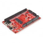
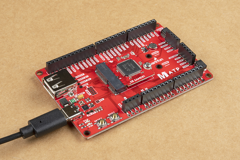
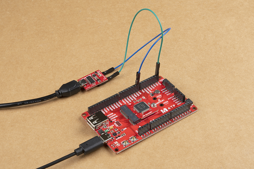
For simplicity, we'll be using the MicroMod ATP Carrier Board to program the board. At a minimum, your setup should look like the image below with the MicroMod SAMD51 inserted into the MicroMod ATP Carrier Board with a USB-C cable.
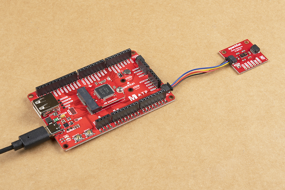
If you decide to use a Qwiic device (because why not?!), simply insert a Qwiic cable between the two connectors.
The SAMD51 Processor Board is easy to program thanks the UF2 bootloader. With the UF2 bootloader, the MicroMod SAMD51 Processor Board shows up on your computer as a USB storage device without having to install drivers for Windows 10, Mac, and Linux!
UF2 stands for USB Flashing Format, which was developed by Microsoft for PXT (now known as MakeCode) for flashing microcontrollers over the Mass Storage Class (MSC), just like a removable flash drive. The file format is unique, so unfortunately, you cannot simply drag and drop a compiled binary or hex file onto the Turbo. Instead, the format of the file has extra information to tell the processor where the data goes, in addition to the data itself.
For Arduino users, the UF2 bootloader is BOSSA compatible, which the Arduino IDE expects on ATSAMD boards. For more information about UF2, you can read more from the MakeCode blog, as well as the UF2 file format specifiation.
The bootloader is what allows us to load code over a simple USB interface. To upload code, you will need to manually enter bootloader mode by rapidly double-tapping the reset button (after hitting the reset button once, you have about half a second to hit it again). The board will remain in bootloader mode until power cycles (happens automatically after uploading code) or the reset button is hit again (once).
On the SAMD51, the there are a clues to if it is in bootloader mode:
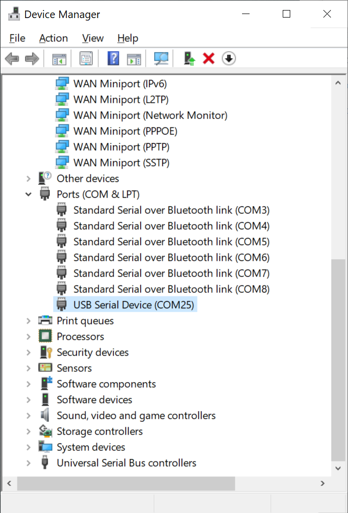
To verify that your driver is working, you should see the difference in the following pictures after plugging in your SparkFun MicroMod SAMD51 Processor Board. Alternatively, once you have the Arduino IDE installed, you should also see a change in the number of available Serial/COM Ports (you may need to restart the Arduino IDE for the board to populate).
Check that the board shows up in your device manager. You can click the Start or ⊞ (Windows) button and type "device" to quickly search for the application. (*On Windows 10, the quick search function is picky on the spelling of the application you are searching for. For example, you may get results using "devi" and none for "device".)
Open the Terminal and run the following command ls /dev/cu.* in the Terminal and check for the following changes (your board may show up under a different device name). To open the Terminal, open your Applications folder, Utilities folder, then double-click on Terminal. Otherwise, press ⌘ (Command) + space bar (Space Bar) to launch Spotlight and type "Terminal," then double-click the search result.
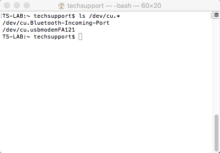
ls /dev/cu.*
Run the following command ls /dev/ttyACM* in the CLI/Terminal and check for the following changes (your board may show up under a different device name).
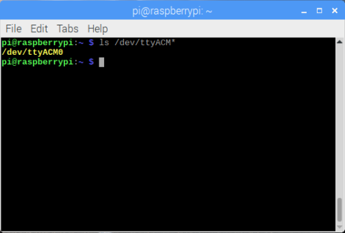
ls /dev/ttyACM*
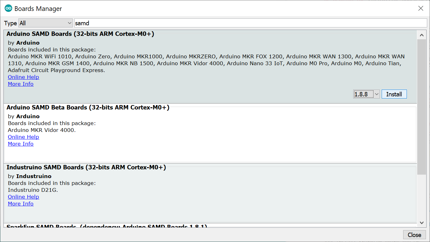
First, you'll need to install a variety of tools, including low-level ARM Cortex libraries full of generic code, arm-gcc to compile your code, and bossa to upload over the bootloader. These tools come packaged along with Arduino's SAMD board definitions for the Arduino Zero.
To install the Arduino SAMD board definitions, navigate to your board manager (Tools > Board > Boards Manager...), then find an entry for Arduino SAMD Boards (32-bits ARM Cortex-M0+) by typing SAMD in the search bar. Select it, and install the latest version (at the time of writing this tutorial, the board definitions work with v1.8.9).
Downloading and installing the tools may take a couple minutes -- arm-gcc in particular will take the longest, it's about 250MB unpacked.
Once installed, Arduino-blue "Installed" text should appear next to the SAMD boards list entry.
Now that your ARM tools are installed, one last bit of setup is required to add support for the SparkFun SAMD boards. First, open your Arduino preferences (File > Preferences). Then find the Additional Board Manager URLs text box, and paste the below link in:
language:bash
https://raw.githubusercontent.com/sparkfun/Arduino_Boards/main/IDE_Board_Manager/package_sparkfun_index.json
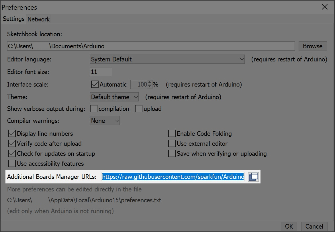
Then hit "OK", and travel back to the Board Manager menu. You should (but probably won't) be able to find a new entry for SparkFun SAMD Boards. If you don't see it, close the board manager and open it again. ¯\_(ツ)_/¯.
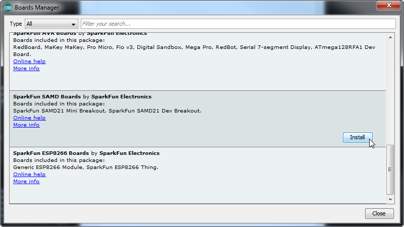
This installation should be much faster; you've already done the heavy lifting in the previous section. When writing this tutorial, the board version used in this tutorial should be v1.7.6. You may have a higher version as the board if there are any updates.
Once the board is installed, you should see a new entry in your Tools > Board list. Select your SparkFun MicroMod SAMD51.
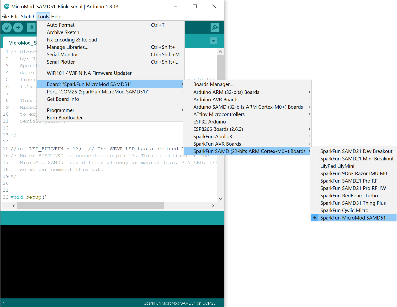
Finally, select the SparkFun MicroMod SAMD51's port when the board is connected to your computer. Navigate back up to the Tool > Port menu. The port menu will have the SparkFun MicroMod SAMD51's port, labeled as such here. On a Windows machine, the serial port should come in the form of "COM#". On a Mac or Linux machine, the port will look like "/dev/cu.usbmodem####".

In the picture above my MicroMod SAMD51 is listed under COM25; this is because I've plugged in about as many microcontrollers into my computer, but the one in your port menu should be smaller.
The SAMD51 is a powerful microcontroller. Here are a few examples that highlight some of its functionality.
Now that you have a Processor Board secure in the Carrier Board, let's upload a combined sketch to the board. We will combine the blink and Hello World! sketches into one. Copy and paste the following code in the Arduino IDE. Head to Tools > Board to select the correct board definition (in this case, SparkFun MicroMod SAMD51). Select the correct COM port that the board enumerated to. Hit upload.
language:c
/* MicroMod SAMD51 Blink and Serial Test Code
by: Ho Yun "Bobby" Chan
SparkFun Electronics
updated: November 5, 2021
date: October 7, 2020
license: Public Domain - please use this code however you'd like.
It's provided as a learning tool.
This code is provided to show how to control the SparkFun
MicroMod SAMD51's STAT LED within a sketch. It also serves
to explain the difference between Serial.print() and
Serial1.print().
*/
//int LED_BUILTIN = 13; // The STAT LED has a defined Arduino pin
/* Note: STAT LED is connected to pin 13. This is defined in the
MicroMod SAMD51 board files already as macros (e.g. PIN_LED, LED_BUILTIN)
so we can comment this out.
*/
void setup()
{
pinMode(LED_BUILTIN, OUTPUT); // Set RX LED as an output
// TX LED is set as an output behind the scenes
Serial.begin(9600); //This pipes to the serial monitor
//while (!Serial) ; // Wait for Serial Monitor to open for Processors with Native USB
Serial.println("Initialize Serial Monitor");
Serial1.begin(9600); //This is the UART, pipes to sensors attached to board
Serial1.println("Initialize Serial Hardware UART Pins");
}
void loop()
{
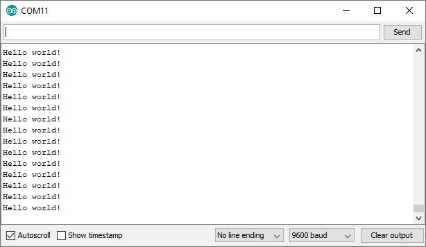
Serial.println("Hello world!"); // Print "Hello World" to the Serial Monitor
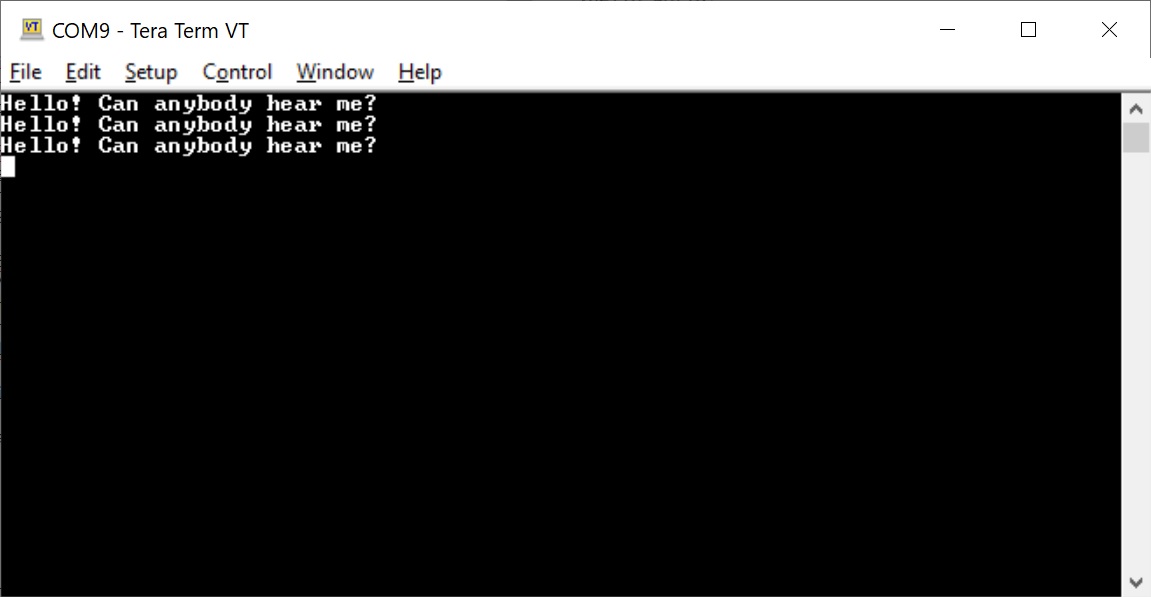
Serial1.println("Hello! Can anybody hear me?"); // Print "Hello!" over hardware UART
digitalWrite(LED_BUILTIN, LOW); // set the LED_BUILTIN ON
delay(1000); // wait for a second
digitalWrite(LED_BUILTIN, HIGH); // set the LED_BUILTIN OFF
delay(1000); // wait for a second
}
Check out the MicroMod SAMD51's built-in LED. The LED should blink every second.
Open the Arduino IDE's serial monitor set at 9600 baud. You should see every programmer's favorite two-word phrase.
Want to go the extra mile? Grab a 3.3V USB-to-serial converter (in this case, we are using the Serial Basic Breakout CH340). Then connect GND to GND using a M/M jumper wire. Add another M/M jumper wire between TX from the MicroMod ATP Carrier board and the RXI pin of the USB-to-serial converter. Connect the appropriate USB cable to the USB-to-serial converter.
Open another serial terminal (in this case, we'll use Tera Term on a Windows) and connect to the USB-to-serial converter at 9600 baud. You should see a different message being sent from the hardware serial pin.
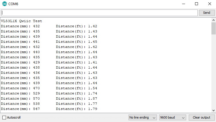
There's a plethora of Qwiic-enabled devices available to connect. In this example, we will be using a Qwiic distance sensor to test. If you have not already, head over to the Qwiic Distance Sensor's (VL53L1X) tutorial to install the library.
Connect the distance sensor to the Qwiic connector. Make sure to connect to the one labeled I2C. There is a second port labeled as I2C1. You would need to adjust the code in order to use the second I2C port.
For simplicity, we'll use the first example just like the tutorial. Open up the first example by heading to File > Examples > SparkFun VL53L1x 4M Laser Distance Sensor > Example1_ReadDistance. If you have not already, head to Tools > Board to select the correct board definition (in this case, SparkFun MicroMod SAMD51). Select the correct COM port that the board enumerated to. Hit upload.
Open a the Arduino Serial Monitor at 9600 baud and start moving your hand over the sensor.
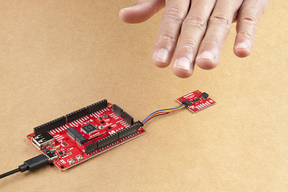
You should see an output similar to the image below. The values will vary depending on the distance away from the sensor.
What's next? Try combining the distance sensor example with the HID keyboard/mouse library to wake up a Raspberry Pi from it's screensaver whenever an object is in front of the sensor. Better yet, try adding some buttons and writing code to make a game controller for a computer.
Now that you've successfully got your MicroMod SAMD51 Processor Board up and running, it's time to incorporate it into your own project! For more information, check out the resources below:
Need some inspiration for your next project? Check out some of these related tutorials using HID mouse/keyboard or adding more SERCOM Ports for your SAMD51:
Or check out other tutorials with MicroMod:
learn.sparkfun.com | CC BY-SA 3.0 | SparkFun Electronics | Niwot, Colorado